Search
Call for Live Order Assistance & Technical Support (7:30am-5pm CST)
All Categories
    Menu Close
    RSS

    Blog

    Sprayer Operations: Manual vs Automatic Rate Control

    When it comes to sprayers, planters, and other liquid application equipment, choosing between automatic and manual rate control is one major aspect that has a massive impact on the convenience and efficiency of your system. Each option offers advantages depending on your operation's needs, equipment, and budget. This blog will break down the key differences between these systems, how each one works, and the pros and cons of both to help you make an informed choice between the two.


    Example of Common Sprayer Controls


    What is Rate Control?

    At its core, rate control refers to how the system manages the volume of liquid applied per acre. Precise control ensures that chemicals are applied at the correct rate, avoiding under-application that could harm yields or over-application that could waste inputs and increase costs.

    All rate control systems fit into two primary categories: manual and automatic control. The fundamental difference lies in how the system adjusts flow rates as ground speed changes. While automatic systems adjust the flow in real-time as you change speed, manual systems require you to adjust flow settings yourself. Let's dive deeper into each approach.


    Manual Rate Control: Simplicity at a Lower Cost

    Manual systems rely on the operator to adjust the application rate manually, either by changing the pressure in the system with a regulating valve or by controlling the speed of the pump motor/drive. This setup is typically much simpler and budget-friendly but requires more hands-on monitoring and manual adjustment during operation.

    manual sprayer rate controller

    How Manual Rate Control Works

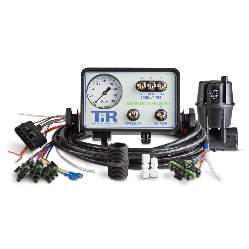
    Manual rate control systems achieve the desired output primarily through two methods: varying pressure with a regulating valve or adjusting the speed of a pump motor/drive. Both approaches require hands-on operation and frequent adjustments to maintain accurate application rates.

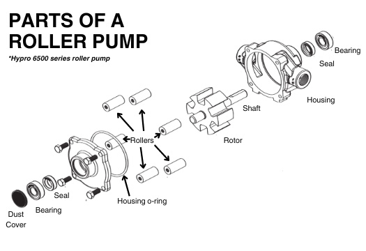
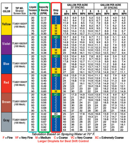
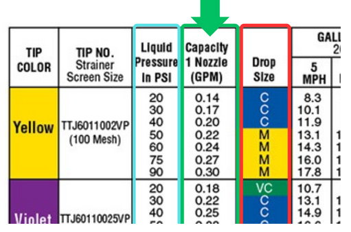
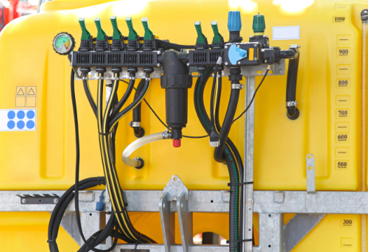
    The first method involves varying pressure using a manual regulating or bypass valve. In this setup, the operator sets the system’s pressure to match the desired application rate. For example, you might calculate that at 5 mph, 28 PSI is needed to deliver 10 gallons per acre (GPA). However, if your speed increases to 6 mph, you must manually increase the pressure to 33 PSI to maintain the same 10 GPA (these numbers are just examples). This method demands careful pre-calculation of operating pressures for different speeds, along with frequent adjustments throughout the application process.

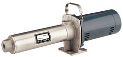
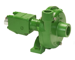
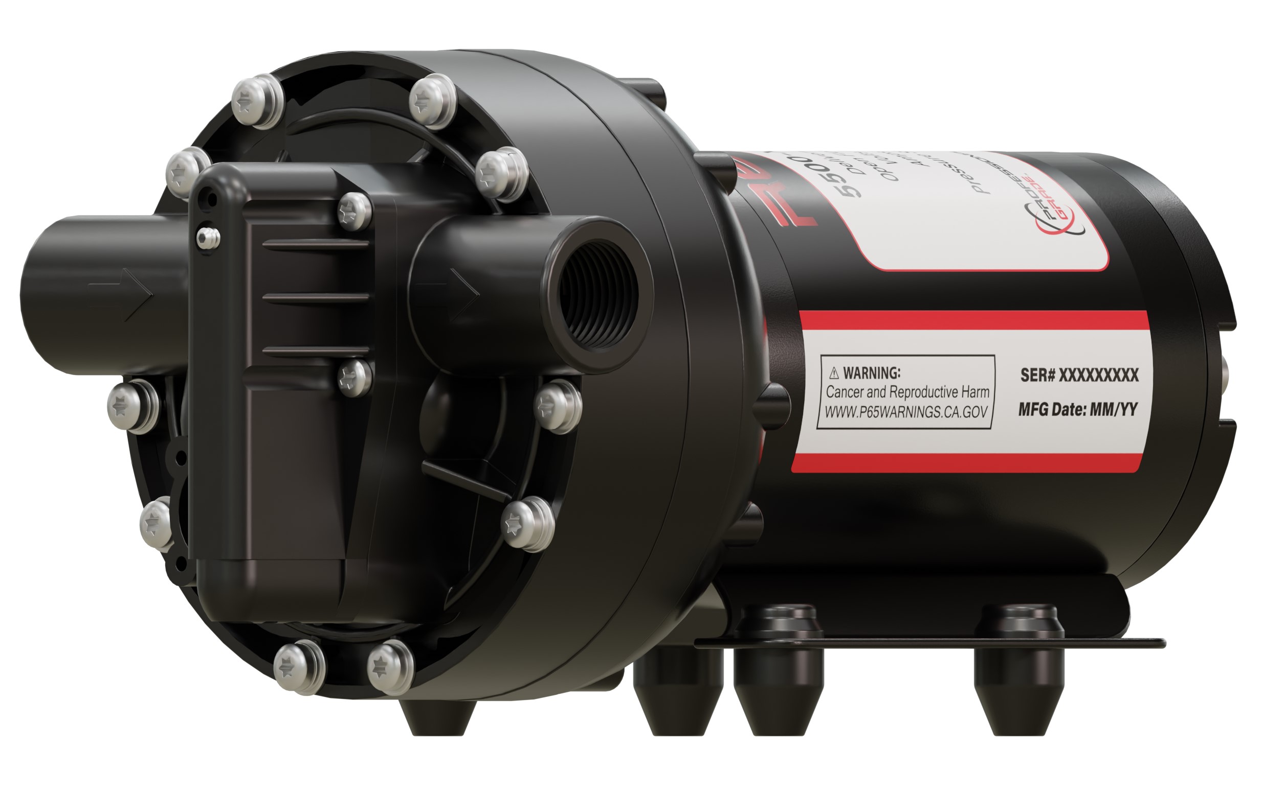
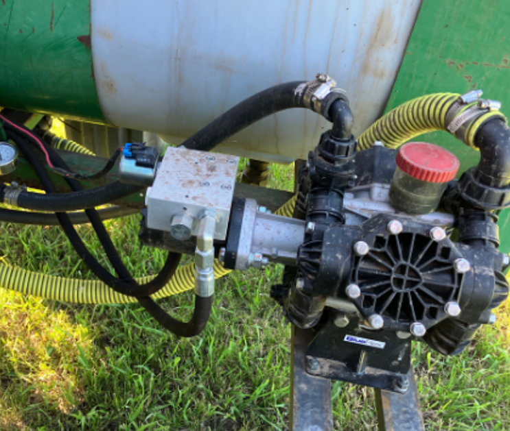
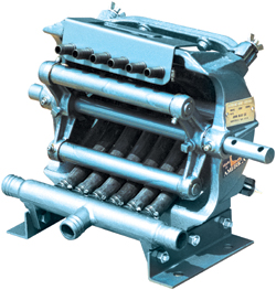
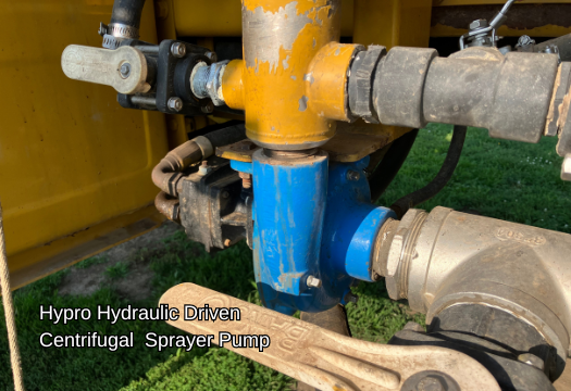
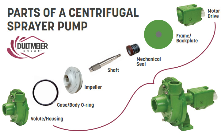
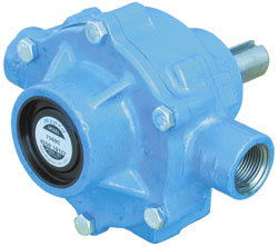
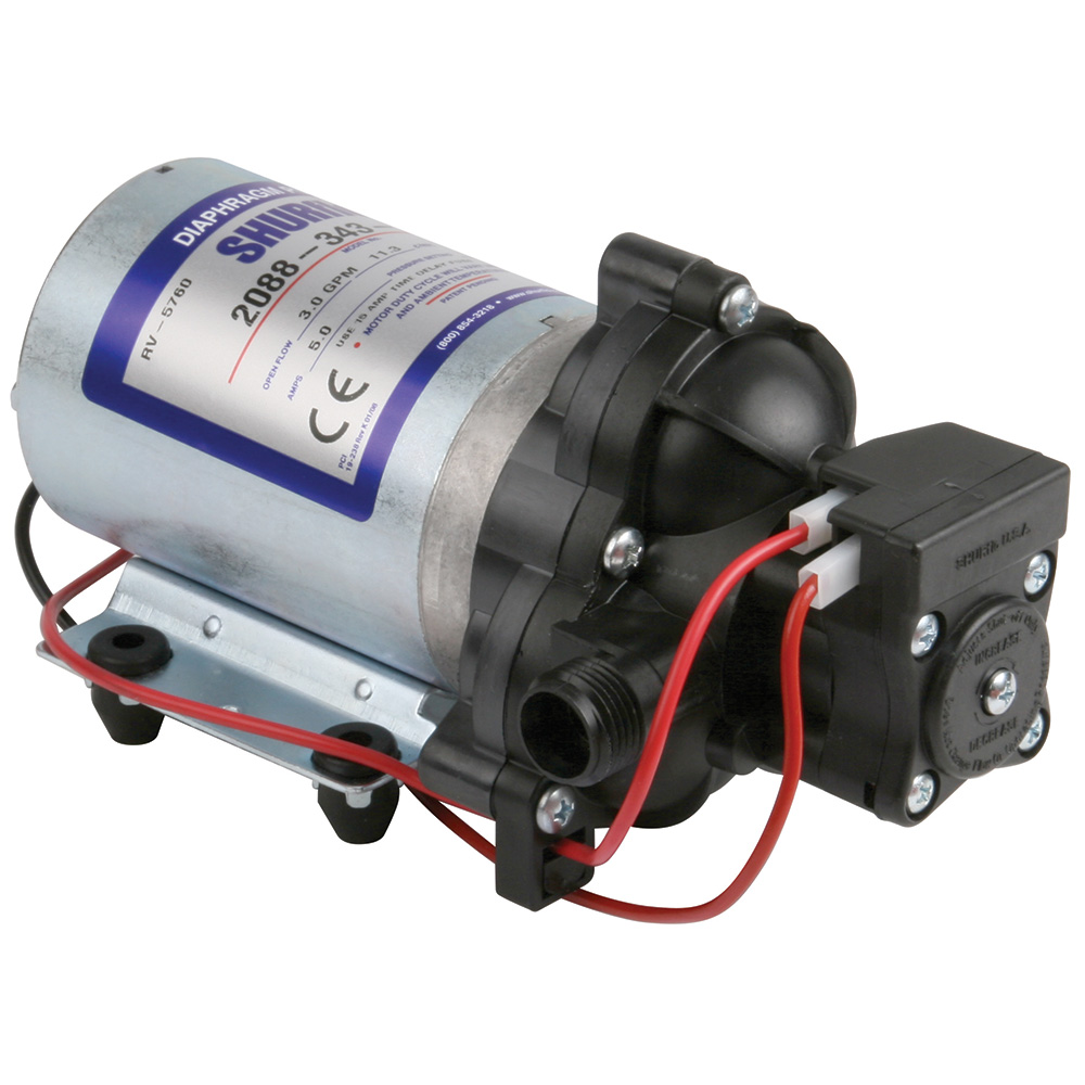
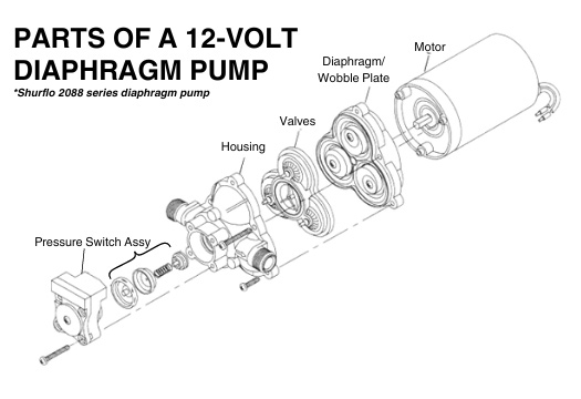
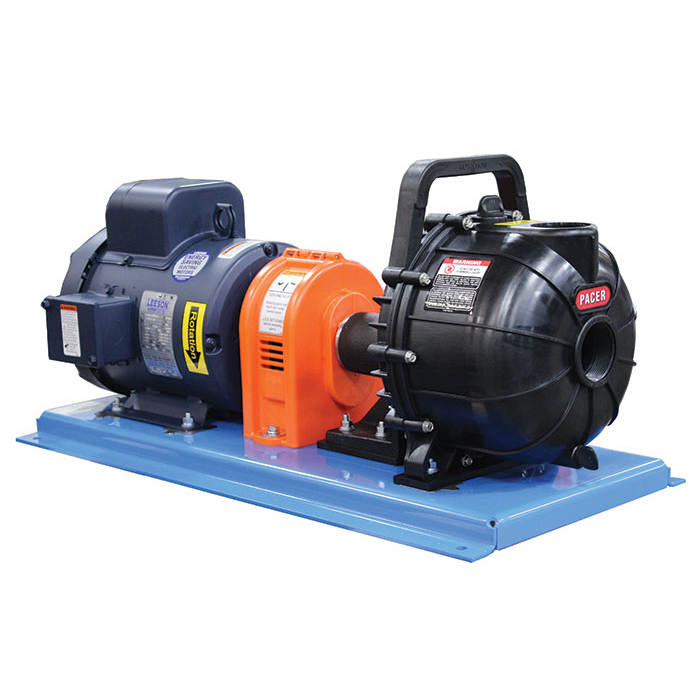
    The second approach involves using a mechanism to adjust the speed of the pump. Two common methods are using a rheostatic control to adjust the RPM of a 12-volt electric pump or a PWM valve to vary the flow of a hydraulic pump. These systems allow the operator to increase or decrease the pump’s speed to control flow rates. 

    While the flow can be adjusted in real-time, it still requires manual input based on changes in ground speed. If you speed up, you need to increase the pump RPM to keep the application rate consistent, and if you slow down, you must decrease the RPM to avoid over-application.

    For more details, you can examine the manual rate control plumbing diagrams here.


    Pros and Cons of Manual Rate Control

    Pros:

    • Lower upfront cost: Fewer components mean a more affordable setup.
    • Simplicity: Easier to install and maintain with fewer parts to troubleshoot.
    • Flexible with smaller operations: Suitable for fields where speed changes are minimal or predictable. Best option for skid sprayers or turf sprayers that utilize a spray gun rather than a boom. 

    Cons:

    • Labor-intensive: Requires constant monitoring and adjustment, which can be challenging when the operator has multiple things to monitor in the sprayer/tractor cab.
    • Inconsistent applications: Greater risk of  over- or under-application due to human error  
    • Less efficient: Not ideal for operations where speed frequently changes, like irregular terrain or fields with obstacles. Not ideal for prescription applications. 

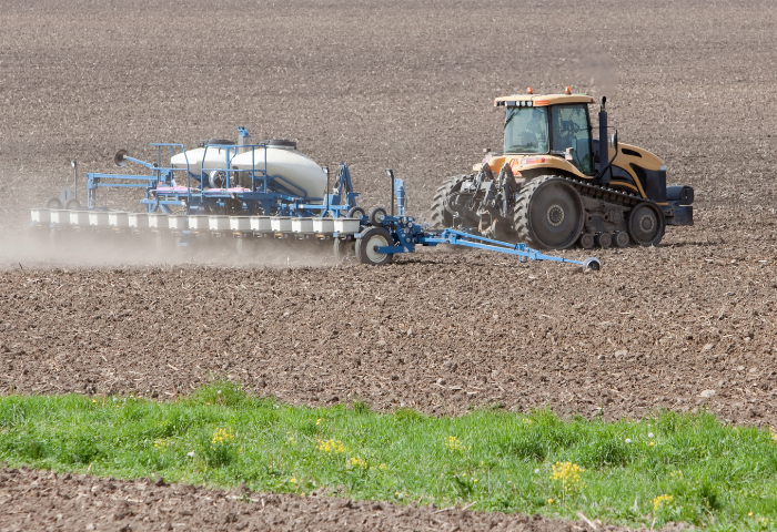
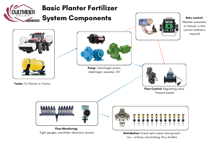
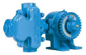
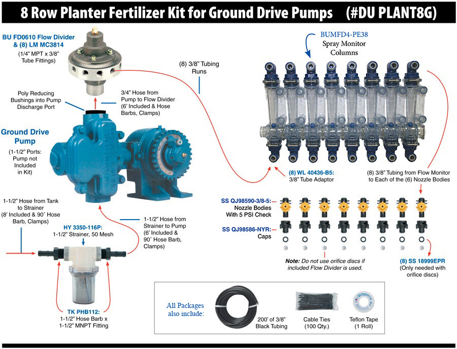
    You can see more information about setting up simple and cost-effective manual rate control in this article about planter fertilizer systems.


    Automatic Rate Control: Precision and Convenience

    Unlike manual rate control systems where the operator constantly must monitor speed and adjust as best they can to changes in the field, automatic rate control systems take the guesswork out of fertilizer and chemical applications. These systems are designed to automatically adjust flow rates as ground speed changes. This type of control is especially necessary in larger operations requiring maximum efficiency.


    automatic rate controller


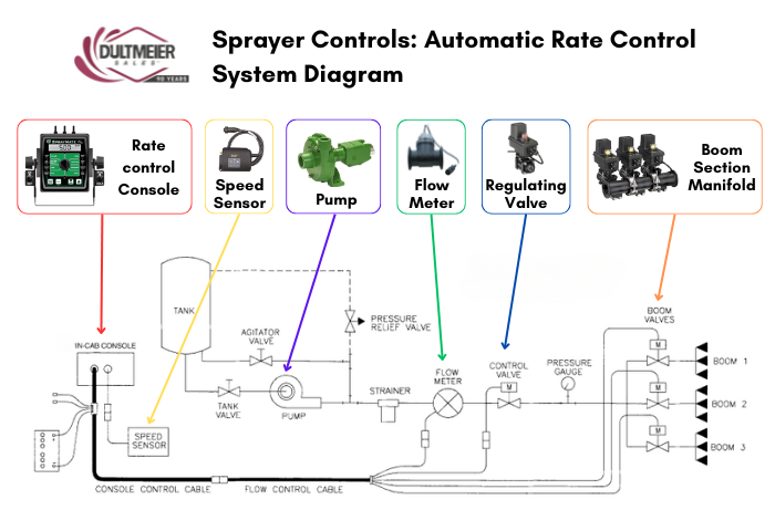
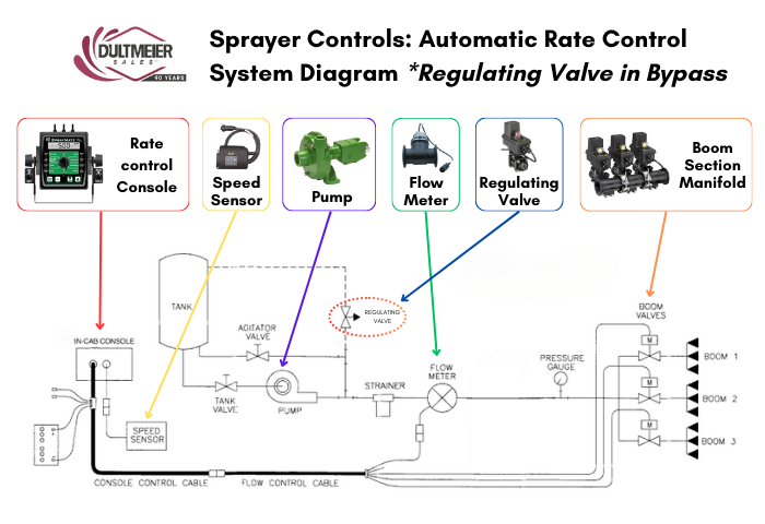
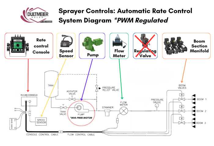
    How Automatic Rate Control Works

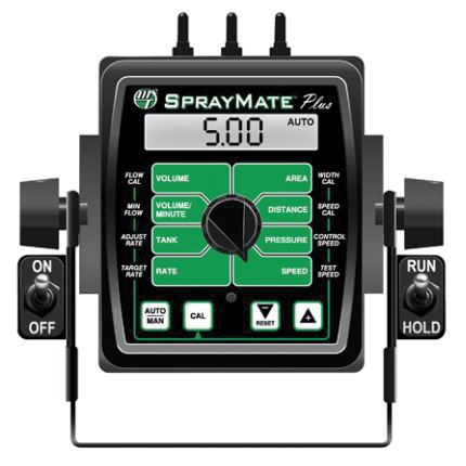
    Automatic rate control systems rely on sensors, controllers, and flow meters to monitor both ground speed and flow rate in real-time. As the system detects changes in speed—whether from variations in terrain or adjustments made by the operator—it automatically adjusts an electronic regulating valve (or PWM valve/motor) to maintain a consistent application rate, typically measured in gallons per acre (GPA).

    These systems remove the need for manual input during the application, which frees up the operator to check for plugged nozzles, monitor wind conditions, and obviously steer. Many automatic rate control systems are integrated with GPS or in-cab monitors to enhance precision further. 

    If you want more information then check out our article on the components needed for automatic rate control on a sprayer. 

    Pros and Cons of Automatic Rate Control

    Pros:

    • Highly accurate applications: Reduces waste and ensures nutrients or chemicals are applied at the correct rate across the entire field.
    • Increased efficiency: Operators can focus on other aspects of operation instead of manually adjusting settings.
    • Ideal for large-scale operations: Handles varying speeds and field conditions seamlessly.

    Cons:

    • Higher cost: Advanced components like sensors, monitors, and GPS integration increase the upfront investment.
    • More complex setup: May require professional installation and calibration
    • Potential for downtime: Malfunctioning sensors or controllers can be more difficult to troubleshoot and halt operations until repaired.


    Conclusion: Which System is Right for You?

    Choosing between manual and automatic rate control depends on the specific needs of your operation. Manual systems offer a cost-effective solution for small farms, acreages, pastures, sports fields, etc. Basically, anywhere you can maintain a fairly constant speed on level terrain. On the other hand, automatic systems are ideal for large-scale or precision farming operations where efficiency and accuracy are paramount, though these systems come with higher upfront costs and more complex maintenance.

    No matter which route you choose, Dultmeier Sales can help you identify the system that will meet your needs. Give us a call today and we’ll happily help you determine the best option for your operation.

    ⇒ Browse the Different Rate Control Options Available At Dultmeier Sales


    Shane Blomendahl, Author

    Tech Ag & Industrial Sales

    Shane Blomendahl is a tech sales veteran at Dultmeier Sales with over 10+ years of experience in liquid handling products covering several industries and applications.

    Learn More About Author

    (0) Sprayer Setup: Components Needed for DIY Automatic Rate Control

    Operating a sprayer from the cab of a tractor or other vehicle sometimes requires more than two hands, between adjusting pressure, changing boom height, ensuring nozzles don’t plug, not to mention steering. This can make it difficult to monitor and maintain your desired application rate. That’s where automatic rate control comes into play.

    With the proper components, you can set your desired application rate (gallons per acre/ gallons per lane mile, etc.) and let the sprayer maintain this rate as conditions or speed change. This is a pretty standard feature on large-row crop sprayers, but it is possible to incorporate auto rate control into just about any type of broadcast sprayer. 

    Today, we will examine how these systems work, the various components required, and how they fit together to accurately maintain the output of your sprayer.


    Image of a tractor in the field with spraying equipment, ready to spray


    Defining Automatic Rate Control on Sprayers

    Automatic rate control refers to the ability of a sprayer to change the volume of fluid dispersed in a given amount of time to maintain a preset application rate without manual adjustments by the operator. This is accomplished via a combination of specific components working together. The operator sets their parameters, and these sprayer controls are then able to accurately deliver the desired result. 

    Automatic rate control offers several advantages over less sophisticated manual sprayer controls such as having significant improvement in your accuracy, efficiency, and cost-effectiveness of agricultural spraying operations. 


    Advantages of Automatic Sprayer Rate Control

    • Accuracy: Real-time adjustments for precise application, reducing human error and ensuring consistent coverage across varying speeds and terrain.
    • Efficiency: Minimizes over-application and under-application, optimizing the use of chemicals, fertilizers, and water.
    • Cost Savings: Reduces product wastage, lowering input costs by applying only the necessary amount of liquid over the target area.


    Pressure Versus Flow Meter Based Rate Control

    When discussing automated sprayer controls, it is important to note that the output or application rate of a sprayer can be managed in two distinct ways: pressure-based control and flowmeter-based control. In pressure-based systems, the sprayer’s application rate is controlled by monitoring and adjusting the system’s pressure with a regulating valve to increase or decrease the sprayer's output.

    In flow meter-based systems, the application rate is controlled by using a flowmeter to precisely measure the amount of liquid flowing through the system and using a valve or pump speed control to adjust the volume of liquid.

    Both methods can be used to automate a sprayer's output, but the necessary components and overall system are slightly different. At Dultmeier Sales, we tend to see flow meter-based control systems more often, and that is what we will focus on in this article. 


    Key Components of an Automatic Rate Control System

    There are many ways one can go about setting up a sprayer. Pressure sensors, agitation, tank monitors, air clean out, boom section valves, etc. These pieces add valuable features, but they are not all required for the sprayer to monitor and maintain a rate automatically. The base components that are needed for a flow meter-based automatic rate control system include a rate controller, flow meter, regulating valve, and speed/GPS sensor

    There are several variations of each component in terms of size, design, and brand, but they all work together in the same basic way. As the sprayer moves through the field, the speed sensor continuously updates the rate controller on the ground speed. The flow meter measures the actual liquid flow, and the rate controller compares this with the desired rate. If adjustments are needed, the controller instructs the pump or regulating valve to modify flow.


    Automatic Rate Control System Setup

    Each piece needed to automatically adjust your sprayer’s rate is important, but it is also just as important to install them in the correct way. In the image below, you can see a basic sprayer plumbing layout for a flow meter-based automatic rate control: 


    Fig. 1 for Sprayer Automatic Rate Control Setup


    The control console will require a wiring harness that connects to the flow meter (or PWM valve/motor - more on this below), a regulating valve, and the boom section valves (if applicable). The GPS radar or speed sensor will also connect to the rate control console. 

    In the diagram, the flow meter is installed after the pump and prior to the regulating valve. This flow meter must be on the pressure or discharge side and the plumbing after it must be solely supplying the boom. This way it can tell the control console the exact rate of fluid being applied. 

    The regulating valve could be installed before the flow meter, but then the adjustments from the regulating valve would disturb the steady flow of liquid and potentially cause inaccurate readings from the meter. 

    Another option is to install the regulating valve in a return line to the sprayer tank. Again, there are several different ways to accomplish this, but the basic setup would look like this: 


    Fig. 2 for Sprayer Automatic Rate Control Setup


    Although boom section valves are not necessary for auto rate control, rate control consoles often come with boom section switches to control multiple valves. If you have a GPS-guided/mapping system, the section valves can be opened/closed automatically by the console.  

    As referenced earlier, there are several different types of each component, size, types, brands, etc. Different brands can typically communicate with one another, you just need to ensure you have the proper wire harness and adapters. 

    If you are unsure about a valve, flow meter, or other parts working together, give us a call. We can help with Raven, Micro-Trak, and TeeJet systems for agriculture, de-ice, and several other types of sprayers. 

    Now let’s look at each piece of the puzzle a little closer.

    Rate Controller

    The rate controller is the "brain" of the entire system. It contains the electrical programming to process the data it receives from the flow meter and speed sensor and uses this information to adjust the flow by controlling the regulating valve or PWM (Pulse Width Modulation) valve or motor depending on the setup.

    To do this the rate controller needs to know certain information. The operator supplies it with the desired application rate and the spacing of the nozzle on the spray boom. To make the proper adjustments as the speed changes, the controller must also be able to know the travel speed of the sprayer and the flow rate of liquid through the system. This is where the speed sensor/GPS sensor and flow meter come into play.


    Recommended Rate Controllers:

    Teejet 845: The 845 sprayer control is an easy rate controller to program and features five boom section valve switches, PWM pump control, and options for variable rate control.

    Micro-Trak Spray Mate: The SprayMate II is a compact controller that offers lots of operator-minded/user-friendly features to control multiple rates on the go. Micro-Trak’s SprayMate Plus offers both flow and pressure-based control as well as PWM compatibility.

    Raven 450: SCS 450 rate controllers provide feedback on a variety of spraying information such as total volume applied, total area covered, distance traveled, area covered per hour, and more. Works with regulating valves and PWM systems. Integrates seamlessly with other Raven products.


    Flow Meter

    Flow meters are a fundamental component in any automatic rate control system. A flow meter's function is to monitor the flow rate of the liquid being sprayed. It measures the gallons per minute (GPM) flowing through the system and sends this information to the rate controller.

    There are different sizes of flow meters available, and the size corresponds to the flow range that the meter can accurately read. For example, a Raven RFM60P will register flows of 1-55 gallons per minute. This model is a fairly common flow meter for agricultural sprayers. 

    View Flow Meter Options Here


    Pressure Sensors

    In a pressure-based control system, a pressure transducer or sensor would be used to monitor the PSI within the sprayer. The rate controller would make any appropriate adjustments based on this reading rather than a flow meter. Pressure sensors can still be used with a flow meter-based system to monitor the pressure in the system, while the flow meter is used to monitor the rate.


    Speed Sensor / GPS

    Tracking the sprayer's ground speed is another necessary factor in auto rate control. GPS radar receivers register and deliver this data to the rate controller. This input is necessary because the flow rate alone is insufficient for precise control; you also need to know how fast the sprayer travels. Faster travel speeds require a higher volume of liquid output to maintain the same rate. Likewise, a lower volume is needed at slower speeds.

    Most speed sensors use GPS to measure the speed; however, some options do not require a GPS signal and instead measure the rotation of a shaft/wheel. These can work great if you want to avoid investing in a GPS antenna/receiver or are concerned about getting a reliable GPS signal in your area.  

    Speed Sensors Options:


    Regulating Valves

    The regulating valve is the last piece of the puzzle. The rate controller uses the inputs from the flow meter and speed sensor to adjust the regulating valve according to the parameters you set in the controller.

    In most scenarios, the regulating valve is an electric ball or butterfly valve. The electric motor rotates the ball or disc inside to increase or decrease the flow rate as needed. 

    View Regulating Valve Options Here


    PWM Valves/Motors

    Some automatic rate control systems don’t use a regulating valve, and the flow is instead controlled with PWM (Pulse Width Modulation). In these PWM systems, the rate controller adjusts the speed of a pump motor to increase or decrease the flow rate. 


    Fig. 3 for Sprayer Automatic Rate Control Setup


    There are centrifugal, piston, and diaphragm pumps that come equipped with PWM-controlled hydraulic motors. With these types of pumps, the rate controller cable that would normally attach to your regulating valve instead connects to the PWM hydraulic motor:

    You can also buy a PWM hydraulic valve or PWM valve/motor combo to add to an existing pump:


    Key Takeaways

    Although there are several ways to build your system, adding automatic rate control to your sprayer doesn’t have to be complicated. There are simple and affordable options that will give you the efficient and effective control that you desire, and which best suit your unique application needs. This article will help ensure that you have the right set of components and understand the basics of how those individual components work within the larger system. If you need any assistance, we here at Dultmeier Sales are happy to help you get your automatic rate control system up and running.


    If you need assistance setting up your sprayer, don’t hesitate to give us a call
    .

    Spot Free Woes: Troubleshooting Guide for Car Wash RO Systems

    As a car wash owner, you know how frustrating those pesky water spots can be-they're the bane of a perfect wash and can leave customers dissatisfied. Ensuring your RO (Reverse Osmosis) system is functioning properly is crucial to delivering that spot-free shine every time.

    In this guide, we'll dive into the reasons behind Spot Free RO system failures and how to fix the issue, helping you maintain that flawless finish and keep your customers happy. Let's get started on troubleshooting!

    Common RO System Symptoms and What to Do About It

    When your RO system is not performing up to par, there could be several possible culprits. Let's look at some of the most common symptoms you might face, the possible root causes, and how to fix them.

    RO spot free rinse production system diagram

    Symptom: Low Flow or No Water Production

    Possible Cause: Clogged Pre-Filter

    Pre-filters in an RO system are designed to capture large particles, debris, and other contaminants before water reaches the RO membrane. Over time, these pre-filters can become clogged, reducing the system's flow rate and potentially causing a disruption in water production.


    RO spot free rinse pre-filter


    Solution: Inspect and replace pre-filters if necessary.  Check the TDS with a meter to see if the membrane is making acceptable water (learn more about using TDS meter here). Sometimes you can see debris on the incoming side of the membrane when it is removed. If there is no noticeable debris it can be restricted throughout the field of the wrap of the membrane resulting in little to no flow.

    Higher flow and higher TDS on the permeate side usually indicated a fouled or bursting membrane. Before replacing a membrane be sure the water softener is working properly, producing zero grain soft water. The softener brine tank should be cleaned periodically.


    Possible Cause: Low Inlet Water Pressure

    For an RO system to function properly, it requires adequate inlet water pressure. If the water pressure is too low, the membrane will not be able to filter water effectively, leading to reduced flow or complete system shutdown.

    Solution: Make sure the water softener is flowing correctly and that the bypass valve is fully closed. Check all valves ahead of the unit to make sure no shut-off valves are closed or not fully opened.


    Possible Cause: Pump Failure

    The booster pump plays a crucial role in increasing water pressure to the RO membrane. If the pump fails, the system will not have sufficient pressure to produce water, leading to reduced flow or no production.

    Solution: Consult the MFG for troubleshooting help or Dultmeier Sales.


    Possible Cause: RO System in Flush Mode

    Many Spot Free RO systems (like the Dultmeier DUSFR) are equipped with a flush mode, where water is run through the system to clean the membrane. During this cycle, water production will be reduced, and the system will appear to have low flow.

    Solution: Consult your manual to determine how to shut off the flush mode. If you have a Dultmeier RO system, it is equipped with an automatic flush mode. After 3 minutes the system should return to normal operation. If the system does not return to normal operation after this type, examine the flush valve for debris. You can consult the manual for more details on the flush valve location.


    Spot free RO system control panel


    Possible Cause: Incorrect Setting on the Pump Relief Valve

    The pump relief valve controls the pressure within the system. If it is incorrectly set, it can cause either low or excessively high water pressure, both of which can impact water production.

    Solution: Consult the system manual to identify the proper relief valve setting and make any needed adjustments.


    Symptom: Clogged Membrane 

    Possible Cause: Carbon Not Flushed Properly

    The carbon filter in an RO system is designed to remove chlorine, sediments, and organic compounds before the water reaches the RO membrane. If the carbon filter is not flushed properly upon installation or after routine maintenance, carbon particles can pass through to the membrane, leading to clogging.

    Solution: Flush the carbon filter through a full cycle. Check the carbon filter for proper plumbing.


    Possible Cause: Organic or Inorganic Matter in Water Supply

    The incoming water supply can contain organic contaminants (such as bacteria, algae, or plant material) or inorganic materials (such as sand, rust, or other mineral particles) that are too large or difficult for the RO membrane to filter. Over time, these contaminants can accumulate on the membrane surface, clogging it and reducing its ability to filter water effectively.

    Solution: Have water tested before replacing the membrane.

    Managing your RO membranes is vital, for more information, you should read our guide on changing RO membranes


    Symptom: Increased RO Production, High TDS, or Decrease in PSI

    Possible Cause: Membrane installed upside down. 

    The RO membrane must be installed in the correct orientation for water to pass through and filter properly. If the membrane is installed upside down, the flow of water is reversed, preventing the membrane from performing its intended function. This can result in poor water filtration, leading to high TDS levels and increased water production because the system isn't removing contaminants properly.

    Solution: Turn the Membrane in the opposite direction.

    reverse osmosis element/membrane

    Possible Cause: Chlorine in the RO system

    Chlorine is harmful to RO membranes. If chlorine is not filtered out properly by the carbon pre-filter, it can damage or degrade the RO membrane. This leads to poor water quality (high TDS) and often increased water production since the membrane is less effective at filtering contaminants.

    Solution: Inspect, and repair the carbon filter as needed.


    Possible Cause: Ruptured Membrane

    A ruptured membrane can occur due to wear and tear, excessive pressure, or chemical damage (e.g., from chlorine). A ruptured membrane cannot properly filter out contaminants, leading to higher TDS levels and increased water production as the system allows more water to pass through without effective filtration.

    Solution: Shut off the system and remove the membrane from its housing. Inspect the membrane for visible damage, such as tears, holes, or a complete rupture. If the membrane is damaged, it must be replaced immediately. Install the new membrane, making sure it is properly seated in the housing and oriented correctly.


    Did you know Dultmeier Sales keeps a variety of RO membranes and Housings in stock? Be sure to check out the available options for pre-filters, chlorine carbon filters, RO filters, RO membranes, and sediment cartridge filters:


    Reverse Osmosis Systems and Filters


    Symptom: Water Flowing to RO Storage Tank When Unit is Not in Production

    Possible Cause: Debris in inlet solenoid or defective inlet solenoid

    The inlet solenoid valve controls the flow of water into the RO system. If debris clogs the solenoid or if the solenoid is defective, it may not close properly, allowing water to flow into the system even when it should not be producing. This could result in a constant flow of water to the tank, even when the system is not actively producing permeate (filtered water).

    Solution: Remove the inlet solenoid valve according to your system's manual. Carefully inspect it for any signs of debris, dirt, or mineral buildup that may prevent it from closing properly. Use a soft brush or cloth to clean any debris or buildup around the valve. Ensure that the valve can open and close smoothly after cleaning.

    After cleaning, reconnect the solenoid and turn the system back on. Listen for any clicking noises when the system is supposed to open or close the valve. If the valve is not working as expected, it may be defective. If cleaning does not resolve the issue or if the solenoid shows signs of wear, malfunction, or failure, replace the inlet solenoid with a compatible part for your RO system.


    Symptom: Noisy Pump/ Underperforming Pump

    Possible Cause: Inlet is obstructed or restricted

    The pump relies on a consistent and unobstructed flow of water to function efficiently. If the inlet is blocked or restricted by debris, sediment buildup, or a clogged pre-filter, the pump has to work harder to move water through the system. This can result in unusual noises and reduced water flow, leading to underperformance.

    Solution: Remove the prefilter and inspect it for signs of blockage or clogging. Replace the prefilter if it is dirty or past its recommended service life. Inspect the inlet lines for blockages or restrictions. These lines can accumulate sediment or scale, which may impede water flow. Clean the inlet lines by flushing them with clean water. If the lines are severely clogged, they may need to be replaced.

    Booster Pump Part No. SAHP10D


    Possible Cause: Coupling or mounting bolts are loose

    A pump with loose coupling or mounting bolts can cause excessive vibration and noise. Loose bolts can lead to pump wear and potential damage to the housing or connections.

    Solution: Check Coupling Alignment. Inspect the coupling for any signs of wear or misalignment. If the coupling is visibly worn or damaged, replace it. Ensure all bolts securing the pump to the frame or motor are tightly fastened. Avoid over-tightening the bolts, as this could cause damage to the components. Ensure the pump remains securely mounted but allows for the necessary vibration isolation (if designed that way).

    If the pump and motor are not properly aligned, this can cause additional strain on the components and lead to noise. Adjust the pump's position so that it is perfectly aligned with the motor.


    You Can Find RO System Booster Pumps and Repair Parts Here


    Possible Cause: The water source is off or not fully open

    If the water source is not fully turned on or if the water valve is only partially open, the pump may be starved of water. This can cause cavitation inside the pump, which can lead to inefficiency and damage to the pump over time.

    Solution: Ensure that the water source is fully turned on. Sometimes, water valves may appear open but are only partially allowing water through. Double-check to make sure the valve is fully open. Trace the water supply lines leading to the pump and ensure there are no blockages or kinks that might be restricting water flow. This includes valves, hoses, and any filtration units before the pump.


    RO System Maintenance & Troubleshooting Tips

    • Always disconnect the power before attempting any troubleshooting to avoid electric shock.
    • Regularly flush the system to maintain optimal membrane performance and avoid clogs.
    • Replace parts proactively based on the wear or inefficiency noted during daily inspections.
    • Check the prefilter monthly: Replace after approximately 200 gallons or more frequently if needed.
    • Inspect daily for leaks, ensure drain hoses are secure, and check pressure and flow gauges for abnormalities.
    • Test for chlorine using the service valve and a test strip to avoid chlorine damage to the membrane.
    • Monitor TDS levels: The permeate water should have a TDS reading between 0 and 40 ppm. If TDS is above 40 ppm, then the membrane should be replaced. Learn more in our guide on how to test and how often to change RO membranes
    • Inspect the float switch regularly to ensure proper operation.


    Concluding

    Maintaining a spot-free RO system requires regular inspection and cleaning of filters, membranes, and solenoids, ensuring proper water pressure and flow, and securing pump components. Addressing issues like clogged filters, misaligned parts, and proper valve settings prevents noise, low production, and high TDS. Routine maintenance ensures optimal system performance and extends the lifespan of your equipment.

    The Dultmeier Sales Car Wash Tech Team has experience with Spot Free RO systems. Be sure to contact us for more help!

    Best Planter Fertilizer Pump Options
    (0) Best Planter Fertilizer Pump Options

    Whether you plan to use a starter fertilizer or soil biologicals, applying these liquids requires a proper pump. There are many different options available which makes selecting the best option important. Fortunately, most pumps can work in several different applications, the key is identifying a pump that will best handle your liquid, deliver your desired application rate and pressure to fit your system, and provide long-term value.

    The sales crew at Dultmeier has been helping to set up planter fertilizer systems for decades. In this guide, we'll explore the various pump options for planters, delving into the strengths and weaknesses of each. From the high-volume capabilities of centrifugal pumps to the precise metering of piston pumps, and everything in between, we'll cover all you need to know to find options that will best meet your needs.


    Planter and Tractor


    How to Choose a Fertilizer Pump for a Planter

    When using a pump on a planter to apply fertilizer your focus should be on accuracy and reliability. A variety of different pumps can accomplish this, but they achieve this through various means, so that means there are pros and cons to each different type.

    What to consider when comparing different types of fertilizer pumps:

    • Durability: Pumps are made from different materials with varying degrees of resistance or durability when used in rugged conditions with corrosive & abrasive fertilizers.
    • Serviceability: Some pump types are easier to rebuild than others.
    • Flow Rate: There are pumps available to produce varying flow rates, so first determine your required flow rate per minute and identify a pump that will deliver this rate plus some cushion for agitation and increases in speed or application rate.
    • Priming/Suction: Consider the pump's priming capabilities, especially in situations where it needs to draw fertilizer from a tank set below the pump level.
    • Precision: Assess how accurately the pump can deliver the specified amount of fertilizer. Precision is crucial for consistent application and to avoid wastage or crop damage.
    • Compatibility: Ensure the pump is compatible with the type of fertilizer being used. This includes checking for chemical compatibility with the fertilizer to prevent corrosion.
    • Drive Type: Pumps can be driven by different means, such as PTO, hydraulic, or electric motors. Consider the available power sources on your equipment and how the drive type fits into your existing setup.
    • Complexity: Some pumps are more complex in design, requiring more expertise to install and maintain. Simpler designs may be more user-friendly but could lack advanced features.
    • Cost: Balance the upfront cost of the pump with long-term operational costs, including maintenance, repairs, etc. A more expensive pump may offer better durability and efficiency, reducing overall costs in the long run.
    • Fit: Ensure the pump fits physically and functionally with your current equipment. This includes mounting options, connections, and space availability on your planter or tractor.


    Consider the Overall Fertilizer System

    Pumps are just one part of the entire fertilizer application system. The plumbing, control valves, nozzles, etc. work together with the pump to meter and distribute the liquid. The type of pump you use will affect how the rest of the system needs to be put together. The best pump for you will depend on the specific things you need your system to do.

    Choosing the right pump requires that you know what type of system you desire. You might desire simplicity and ease of operation, or you might need more precision and the ability to vary your rate automatically. These pump features along with the available drive type and your budget will ultimately determine the pump that will work best.


    Diagram of Basic Planter Fertilizer System Components


    We go into greater detail on the overall fertilizer system in our guide to planter fertilizer setups, but here are some of the main types of systems and how they differ:

    • 12-volt Pressure Based: a 12-volt pump controlled via a rheostat
    • Ground Drive: pumps driven by planter wheel or ground drive assembly, application rate is maintained automatically as planter speeds up or slows down
    • Automatic Rate Control: The flow rate is automatically controlled with a rate controller, regulating valve, GPS/speed sensor, and flowmeter. Also allows for rate changes from the cab.
    • PWM: automatic rate control with rate controller; pump motor speed is adjusted with a PWM valve or motor instead of using a conventional regulating valve.


    Different Fertilizer Pump Types Used on Planters

    Many of the types of pumps used on planters are similar to those used on a sprayer. There are also pumps designed specifically for planters/toolbars such as squeeze pumps and ground-driven piston pumps. You can see more specific details in our guide to sprayer pumps, but the basic types are:

    Let's examine each type of pump used and identify the scenarios they work for applying fertilizer on a planter.


    Centrifugal Pumps

    The same type of hydraulic-driven centrifugal pumps used on sprayers can be used as a fertilizer pump on a planter. Centrifugal pumps are available that can provide flow rates well over 200 gallons per minute. If you have hydraulic outlets available, then they are a great option, especially for higher volume rates and larger planters.


    Ace FMC-HYD-204 Pump


    For example, if you have a 24-row planter and want to apply a rate of 50 gallons per acre at 5 mph, you need more than 20 gallons per minute from your pump. So, at a minimum, you want a pump that can deliver this flow rate. To be safe you would want a pump that can deliver more than this to account for increases in speed, rate, and agitation.

    Now, when these pumps are used on a sprayer, they are generally handling a liquid that is mostly water. On a planter, you are likely dealing with 100% fertilizer or a diluted solution of fertilizer, water, etc.

    To handle the abrasive and corrosive nature of fertilizers, stainless steel pumps are recommended. Cast iron and poly will work, but they typically do not last as long. While stainless is usually the best option, it does depend upon the specific type of fertilizer or liquid being used. Many centrifugal pump manufacturers, like Ace and Hypro, offer a severe-duty mechanical shaft seal that is made to hold up better to abrasive material. Standard seals will work, but again, they may not last as long.

    It is always vital with a standard centrifugal pump that you don't run it dry. This will knock out the seal quickly. However, there are "wet seal" centrifugal pumps that are protected from running dry. These pumps have a reservoir with a coolant/anti-freeze to lubricate the pump so if the pump is starved of fluid, the seal is still lubricated.

    Pros of Using Centrifugal Pumps for Planter Fertilizer Application:

    • High volume
    • Easy to maintain and rebuild
    • Good for 2x2
    • Long service life, especially stainless steel

    Cons of using a centrifugal pump on a planter:

    • Hydraulic outlets needed
    • Cannot run dry (unless wet seal pump)
    • Straight centrifugal pumps are not self-priming and are limited in where they can be installed.

    System Requirements When Using a Centrifugal Pump:

    Centrifugal pumps need a mechanism to control the flow. Typically, this requires a flow meter, regulating valve or PWM hydraulic motor, along with GPS or speed sensor, and a rate controller. Centrifugal pump setups are relatively more expensive than some other setups.

    For more information on the overall fertilizer setup including controls, monitoring, and metering, refer to our full guide to planter fertilizer systems.

    Centrifugal Pumps Options for Planters:


    Electric Fertilizer Pump for Planter: 12-Volt Diaphragm Pump

    One of the most cost-effective ways to get a starter fertilizer applied is with a 12-volt diaphragm pump. They are especially convenient for someone wanting to add a simple setup to a planter that can be installed easily. 12-volt diaphragm pumps do have some limits. They have a maximum effective flow of about 3-6 GPM. This means they are suited for application rates of up to about 10 GPA for smaller planters (6-12 rows) and about 5 GPA for larger planters (24 row+).


    550 Diaphragm Pump


    12-volt pumps are small and lower cost than other types of pumps. They can be easily installed about anywhere you can supply 12-volt power. It is also easy to adjust the pump output using a rheostat motor controller. This simple controller lets you increase or decrease the pump output from the cab as you speed up or slow down.

    Advantages of 12-Volt Diaphragm Pumps:

    • Low cost relative to other pump types
    • Simple and easy to install

    Disadvantages of Diaphragm Pumps for Fertilizer:

    • Lower flow compared to other pump types
    • Typically do not last as long as other pump types

    System Requirements for 12-Volt Diaphragm Pumps:

    A complete setup requires a pump speed controller, flow monitors, and orifice discs to regulate the output of the pump and apply the correct amount of liquid. This is one of the simplest and lowest-cost ways to apply a starter fertilizer in-furrow.

    Dultmeier offers 12-volt pump kits that include the pump, monitors, speed controller, and plumbing components to install on your planter. Be sure to check this page for a complete list of the kit components. Don't worry we can make any changes to the kit if you need it!


    Hydraulic Driven Diaphragm Pumps

    12-volt electric is not the only type of diaphragm pump that can be used to apply fertilizer. A larger, high-pressure diaphragm pump is another option that delivers more flow and much higher pressures than the small 12-volt motor versions.


    PWM hydraulic motor driven diaphragm pump on planter


    These pumps have excellent suction lift, meaning more flexibility where they are installed vs centrifugal pumps that need to be flooded. These pumps can handle thick and viscous fertilizers with high solid content. The gearbox is lubricated with oil. There is virtually no concern if you run the pump dry.

    This type of diaphragm pump can be driven via a number of different means. Ground drive, engine, etc. The most common option on planters is a hydraulic motor. This may be a conventional hydraulic motor or PWM controlled motor.

    Advantages of Diaphragm Pumps:

    • High volume potential
    • Higher pressure capability compared to other pump types
    • Self-priming
    • Can run dry
    • Ability to handle viscous products

    Disadvantages of Diaphragm Pumps for Fertilizer:

    • Lower flow compared to centrifugal pumps
    • Requires pressure relief valve
    • Routine maintenance required

    Diaphragm Pump System Requirements:

    A diaphragm pump setup will require a rate controller with a flow meter and a regulating valve to control the amount of fertilizer you apply. Diaphragm pumps with PWM hydraulic motors are also available. With PWM you still need the controller and flow meter but instead of using a regulating valve to control flow, the PWM controls the speed of the pump.


    Piston Pumps

    Piston pumps are another type of positive displacement pump used in several different industries. As you might have guessed, a piston pump gets its name from the mechanical means used to move the fluid. In this case, a reciprocating piston forces draws liquid in and forces it out of the pump chamber.


    There are specific piston pumps designed for the agriculture world. The NGP series piston pump from John Blue is an extremely effective tool for liquid fertilizer application on planters, side dress machines, and other toolbars. They offer a very accurate way to apply fertilizers at a constant rate. These pumps can be driven in several ways, but the most common drive types when used on planters are ground drive and hydraulic drive.

    Advantages of Piston Pumps for Fertilizers:

    • Priming Capability - these pumps can prime or pull liquid from longer distances when compared to other pump types.
    • Extremely accurate despite varying temperatures
    • Auto-adjusting for speed changes (maintains application rate)
    • Constructed of durable cast iron and stainless components. Properly maintained pumps can last many years.
    • Field Serviceable

    John Blue Piston Pump Service & Repair Video:


    Disadvantages:

    • Gritty products can damage pistons
    • Lower flow compared to centrifugal pumps

    Piston Pump System Requirements

    As mentioned earlier, there are two main ways to drive a piston pump: ground drive or hydraulic.

    Ground drive either with a dedicated ground drive assembly or planter hex shaft. Ground drive pumps offer extremely accurate performance and do not require all the electronic components like flow meters, regulating valves, or rate controllers.

    Ground-driven pumps do require that you calculate the proper pump setting and select sprockets to ensure the crankcase of the pump is rotating at the speed needed to deliver your desired rate. John Blue provides a tool that lets you quickly determine the correct settings with their NGP piston pump setting calculator.

    From there you simply need to ensure that you evenly distribute the liquid among each row. This will require a flow divider manifold or orifice discs as well as a set of site gauges to monitor the flow going to each row.


    John Blue Ground Drive Piston Pump options:

    Ground Drives:

    NGP Piston Pumps with Hydraulic Motor

    If you prefer, you can drive an NGP piston pump with a hydraulic motor. The motors have a PWM valve that allows you to control your rate by varying the speed of the motor. While this method does not require a regulating valve, you will need a GPS/speed sensor and a flow meter in addition to a rate controller.


    Squeeze Pumps

    A squeeze pump is unique in that it is designed specifically for planters. They are effective at accurately and evenly distributing fluid over each row. They do not require any additional components such as rate controllers, regulating valves, distributors, etc. Just typical plumbing and sight gauges if desired.


    Advantages of Squeeze Pumps

    • Simplicity
    • Maintains rate when you speed up or slow down
    • Pump stops when the planter stops

    Disadvantages of Squeeze Pumps

    • Not as versatile as other pump types
    • Limited pump options available (6 row, 8 row, 12 row, 16 row)

    System Requirements for Squeeze Pumps

    A fertilizer setup using a squeeze pump is very simple. The pump is ground-driven, so the output is directly related to the speed of the planter. This means you dial in the output you need, and your desired application rate is maintained. There is no need for regulating valves or electronic flow meters.

    The pump also serves as the manifold that evenly distributes the liquid over each row. The only additional components you need would be flow monitors so you can watch each row for plugs or low flow.


    Conclusion

    In conclusion, selecting the best fertilizer pump for your planter system requires careful consideration of several factors, including the type of fertilizer, flow rate needs, precision, and compatibility with your setup. Each pump type-from centrifugal and diaphragm to piston and squeeze pumps-offers unique strengths and trade-offs. Whether you prioritize high volume, precision desired, or simplicity, there's a pump to meet your specific requirements.

    At Dultmeier, we understand that no two planter setups are exactly the same, and our team has decades of experience helping customers choose the right pumps for their systems. Whether you need a robust hydraulic-driven pump for high-volume applications or a simple 12-volt diaphragm pump for a smaller planter, we're here to guide you through the selection process. Don't hesitate to reach out for personalized recommendations or browse our selection of pumps and complete fertilizer systems to get started!

    (0) Sprayer Pump Breakdown: Understanding the Mechanics & Benefits of Each Type

    A sprayer's job is to distribute fluid over a designated area. No matter what type of sprayer at the center of the system is a pump. There are nearly endless different types of sprayers. They are built for several applications and require different types of pumps to deliver the flow characteristics necessary to complete those different spraying tasks.

    At Dultmeier Sales, pumps are not just the center of a sprayer, they are at the center of our business. We sell, service, and support a wide variety of pumps for all types of sprayers. In addition, we prioritize understanding the different types, how they operate, and what pump works best on different sprayers.

    In this guide, we will look at all the different types of pumps used on sprayers. We will examine how each pump operates and how they compare in terms of flow rate and pressure. In addition, we will offer real examples so you can see exactly how each pump is used. You'll be able to understand what type of sprayer pump will work for your application.

    Different Types of Sprayer Pumps

    While there are several variations of each type, the different pumps used on sprayers are centrifugal, roller, diaphragm, and piston pumps. Each pump is unique in its design and performance. Let's explore each type to understand how they operate and when to use them.

    Centrifugal Pumps

    Hypro Hydraulic Driven Centrifugal Sprayer Pump

    • Pump Family: Centrifugal
    • GPM Range: 0 to 500+
    • PSI Range: 0 to 150

    Centrifugal pumps use an impeller to move water or other fluids by using centrifugal force. They are known for their ability to move high volumes of liquid at relatively low pressure. The most common centrifugal pump type used on a sprayer is a straight centrifugal pump. Self-priming pumps can be used, but a straight centrifugal pump is typically more efficient and capable of developing higher operating pressure.

    A self-priming pump is capped at about 40-60 PSI depending on the specific pump. The straight centrifugal pumps designed for use on sprayers can produce well over 100 PSI. They are intended to accommodate the high travel speeds of self-propelled sprayers combined with the expanded operating ranges of modern sprayer nozzles.

    Common Centrifugal Sprayer Pump Applications

    • Agricultural Spraying: Boom sprayers, fertilizer toolbars, boomless sprayers, fertilizer delivery on planters.
    • Turf and Landscape: Golf course sprayers, sports field sprayers, large acreage sprayers.
    • Industrial Uses: Salt brine trucks and trailers, water trucks for dust control.

    Advantages of Centrifugal Sprayer Pumps

    • High Volume Output: Centrifugal pumps can handle large volumes of liquid, making them suitable for applications requiring substantial flow rates.
    • Durability: These pumps are robust and can handle abrasive and corrosive chemicals, making them versatile for various spraying tasks.
    • Simplicity: The design is straightforward, which makes maintenance and troubleshooting easier compared to more complex pump types.
    • Cost-Effective: Generally, centrifugal pumps are less expensive to manufacture and maintain, providing a cost-effective solution for many users.

    Disadvantages of Centrifugal Sprayer Pumps

    • Low pressure: Centrifugal sprayer pumps have lower pressure capabilities compared to some other types of pumps like piston or diaphragm pumps. While centrifugal pumps can move high volumes of liquid, they do so at relatively low pressures.
    • Cannot Run Dry*: Running a centrifugal pump without fluid can cause significant damage to the pump. A centrifugal pump requires fluid in the pump case to lubricate the seal. *There are lubricated seals or "wet" seal centrifugal pumps that can run dry.

    Centrifugal Pump Drive Types

    Parts of a Centrifugal Sprayer Pump

    Centrifugal Sprayer Pump Parts Breakdown

    • Impeller: The heart of the pump, which is responsible for imparting kinetic energy to the liquid. The design and size of the impeller significantly affect the pump's performance.
    • Casing: Encases the impeller and directs the flow of liquid. It also helps convert kinetic energy into pressure energy.
    • Seal: Prevents leaks and maintains the pump's integrity by keeping the liquid within the system.
    • Suction and Discharge Ports: Inlet and outlet points through which the liquid enters and exits the pump.

    You can find a more detailed examination of centrifugal pump components and how they affect the performance of a pump in this guide to centrifugal pumps for fertilizer.

    View All Centrifugal Pump Options


    Roller Pumps

    Hypro 7560C Roller Pump

    • Pump Family: Positive Displacement
    • GPM Range: 2 to 60
    • PSI Range: Up to 300
    • Applications: Small and medium-sized boom sprayers, turf sprayers

    Roller pumps use rollers inside a cylindrical housing to move liquid. As the rollers rotate, they create a vacuum that draws liquid in and then pushes it out. Roller pumps are very common on 3-point sprayers crop and turf boom sprayers, because they are self-priming, develop consistent pressure, and are less expensive compared to other types of sprayer pumps.

    A roller pump is part of the positive displacement pump family. This means that a consistent volume of fluid is delivered with each cycle (in this case shaft revolution), regardless of the discharge head in the system. Simply put, you can spray at 60 psi if you want because the pump overcomes the restriction in the system. With a centrifugal pump, the system restriction will affect your operating pressure much more.

    The larger roller pumps can produce about 50-60 GPM, limiting the size of the sprayer they can be used on. A roller pump can be repaired but the standard cast iron housings do have a limited life span. Friction eventually wears the pump housing to a point where the pump will no longer work efficiently.

    To combat the wear and corrosion of agrochemicals and fertilizers, there are Ni-resist and Silvercast pump housings that last much longer than the standard cast iron roller pumps.

    Advantages

    • Pressure Output: Capable of producing consistent and generally higher pressure than a centrifugal pump.
    • Self-Priming: Can draw liquid from a lower level, making them easy to start and use.
    • Compact Design: Small and easy to integrate into different spraying systems.
    • Can Be Reversed: Many roller pump models can be reversed so you can drive it either clockwise or counterclockwise. Consult the manual of your specific pump for details.
    • Cost: Less expensive compared to other sprayer pump types. Especially when PTO driven since it does not require an engine or hydraulic motor.

    Disadvantages

    • Wear and Tear: Rollers wear out, especially when used with abrasive chemicals.
    • Limited Flow Rate: Not suitable for applications requiring high flow rates.
    • Maintenance: Regular maintenance is required to ensure optimal performance.
    • Limited Lifespan: Wear and corrosion can increase the Internal clearance between the pump housing and rollers to the point that the pump no longer works effectively.

    Drive Types

    • PTO
    • Belt Driven
    • Electric Motor
    • Gas-Engine

    Parts of a Roller Pump

    Roller Sprayer Pump Parts Breakdown

    • Rollers: The moving parts inside the pump that create suction and discharge action.
    • Rotor: Holds the rollers in place and drives their motion.
    • Housing: Encases the rollers and rotor, providing a sealed environment for the liquid to move through.
    • Shaft: Driven by PTO or motor and spins the rotor.
    • Seals: Prevents leaks and maintains the integrity of the pump system.

    Check out the Different Roller Pump Options


    12-Volt Diaphragm Pumps

    2088-343-135 12 Volt Diaphragm Pump

    • Pump Type: Positive Displacement
    • GPM Range: 1 to 5
    • PSI Range: Up to 100+
    • Applications: ATV/UTV sprayers, spot sprayers, small boom sprayers, low-volume chemical transfer

    12-volt diaphragm pumps are very common and versatile. They are used on small sprayers because they are easy to power with a battery and relatively low in cost. These pumps work well with a wide variety of agrochemicals, cleaners, and other liquids, especially when diluted. They are self-priming, and they can run dry.

    One standout benefit of the 12-volt sprayer pump is the demand switch. This feature shuts the motor off when you close a valve on the discharge side of the pump. When the valve is closed, the pressure increases, tripping the demand switch and shutting off the motor.

    The most common application of this is when you are spot-spraying with a trigger wand or spray gun. When you pull the trigger, your pump turns on, when you release the trigger, the pump stops. This conserves your battery life and prolongs the life of the pump as it only runs when needed.

    A 12-volt diaphragm pump can be used on smaller boom sprayers. However, they may only be able to work on booms with about 5-10 tips depending on the size of the nozzles that you use.

    Advantages

    • Portability: Lightweight and easy to transport, ideal for portable sprayer setups.
    • Self-Priming: Can draw liquid from a lower level, making them easy to start and use.
    • Low Power Consumption: Efficient operation with low electrical power requirements.
    • Chemical Resistance: Can handle a variety of chemicals without damage.
    • Demand Switch: The pump only runs "on demand", when you pull the trigger or open the valve to spray.
    • Low-Cost: Very affordable compared to other pump types.

    Disadvantages

    • Limited Flow Rate: Maximum flow rates are about 5 GPM.
    • Pressure Limitations: Maximum pressure is lower compared to other positive displacement pumps.
    • Pump Life: The pump motor and other components do not have the same lifespan as other pump types. Parts can be replaced but the cost and time to repair may be nearly as much as a new pump.

    Drive Types

    • 12-volt Electric Motor
    • This pump type is also available with 24-volt and 115-volt motors

    Parts of a 12V Diaphragm Sprayer Pump

    12 Volt Diaphragm Sprayer Pump Parts Breakdown

    • Diaphragm/Wobble Plate: This assembly is driven by the motor; it has an eccentric bearing that causes it to "wobble" and this motion creates the suction to pull liquid into the pump and force it out.
    • Check Valves: let fluid flow into the pump and stop it from going back out of the inlet port.
    • Pump Housing: Contains the wobble plate and check valve assembly, and serves as the pump chamber where the liquid is pulled into the pump and forced out.
    • Motor: Powers the movement of the wobble plate.

    View 12-Volt Pump Options.


    Large Diaphragm Pumps

    503GR34GCI Large Diaphragm Pumps

    • Pump Type: Positive Displacement
    • GPM Range: 3-100+
    • PSI Range: Up to 725
    • Applications: Tree spraying, turf sprayers, fertilizer applicators

    Large diaphragm pumps use multiple diaphragms and chambers to move large volumes of liquid at high pressures. These pumps are the preferred tool for long-range or vertical spraying such as tree spraying. The combination of high-flow rate and high pressures, when combined with the right sprayer gun and nozzle, results in a stream of liquid that can be propelled 50 feet or more in the air.

    Video of Diaphragm Pump on Skid Sprayer:

    Diaphragm pumps can also be used on boom sprayers or fertilizer boom sprayers. While they don't offer the same flow rates as a centrifugal pump of similar size, they can be a good option for sprayers or applicators when the fluid being sprayed is too thick or viscous for a centrifugal pump.

    Advantages

    • High-Pressure Output: Capable of producing very high pressures
    • Durability: The flexibility of the diaphragm offers good resistance to a wide range of abrasive and viscous fluids.
    • Chemical Resistance: Can handle a variety of chemicals without damage.

    Disadvantages

    • Cost: More expensive to purchase and maintain compared to smaller pumps.
    • Complexity: More complex design requires more safeguards and proper installation. Troubleshooting can be more complicated than with other pump types.
    • Maintenance: The diaphragms and pump oil must be changed periodically, typically every 500 hours or 3 months of use.

    Drive Types

    • Engine Driven
    • Hydraulic Driven

    Parts of a Diaphragm Sprayer Pump

    • Diaphragms: Multiple flexible membranes that move to create suction and discharge action.
    • Check Valves: Control the flow of liquid into and out of the pump chambers.
    • Pistons: Push and pull the diaphragms to create the necessary suction and discharge, driven by the crankshaft.
    • Crankshaft: Driven by the engine or motor, rotation of the crankshaft drives the pistons
    • Gear Box: Allows diaphragm pumps to be directly driven by a gas engine at about 3600 rpm.
    • Regulator/Control: Serves as the relief valve and provides pressure adjustment. Also directs flow from the pump outlet to different sprayer features such as spray gun, agitation, etc.

    View All Diaphragm Pump Options


    Piston Pumps

    NGP6055 Piston Pumps

    • Pump Type: Positive Displacement
    • GPM Range: Approx 1 to 68
    • PSI Range: Up to 120
    • Applications: Fertilizer application on toolbars or planters.

    A piston pump is more common for fertilizer application than it is for pesticide/herbicide application. They do not offer the flow rates needed for large boom sprayers, and they are not as forgiving to solids or abrasion as diaphragm pumps. However, they excel at delivering fluid accurately and consistently.

    This pump works by using pistons to create a reciprocating motion that draws liquid into the pump chamber on the suction stroke and then pushes it out on the discharge stroke. This mechanism allows the pump to generate consistent flow.

    There are piston pumps that are designed for high pressures (1000 psi +), but the piston pumps used for agricultural applications are geared to precision. They are often ground-driven, which makes them the simplest option for automatic rate control. A ground-driven piston pump does not require flow meters or regulating valves for automatic rate control. As you speed up or slow down the pump delivers the precise amount needed to maintain your application rate.

    These pumps are also available with hydraulic motors and PWM valves. This allows you to control the speed of the pump with a rate controller and flow meter.

    Advantages

    • Accuracy: The pump pushes a consistent amount of fluid with each stroke, especially important when applying fertilizers.
    • Durability: Robust construction for long-lasting performance in harsh environments.
    • Priming: Excellent ability to prime offers flexibility when mounting the pump on a sprayer, toolbar, or planter.
    • Easy to Service: The NGP piston pumps are designed to be field repaired. The check valves can be quickly removed and cleaned or replaced as needed.
    • Self-Adjusting: A ground-driven piston pump automatically adjusts to your speed, delivering the precise amount needed without flow meters or regulating valves.

    Disadvantages

    • Cost: More expensive than other pump types that deliver similar flow rates
    • Complexity: More complex pumps with many components.
    • No solids: Requires filter prior to the inlet to protect check valves and pistons from damage.

    Drive Types

    Parts of a Piston Sprayer Pump

    The piston pumps used for fertilizer application are more complex pumps than some of the other fertilizer pumps. They feature several components but these are the main ones:

    • Plunger: Reciprocating action of piston rod and plunger draws in liquid and pushes it out.
    • Check Valves: Control the flow of liquid into and out of the cylinders.
    • Crankcase: Houses connecting rod and crankshaft

    See all the Piston Pump Drive Options Here


    Key Takeaways

    The type of pump used on a sprayer can have a drastic effect on the performance. Understanding the different types of sprayer pumps and their attributes will ensure you have the best tool for your application. The Dultmeier Sales team has decades of experience and can provide you with insights and guidance in selecting and troubleshooting your sprayer pump.

    (0) High Volume Transfer: Discovering the Pump Types with the Highest Flow Rates

    Choosing the right pump can make all the difference in how smoothly your system runs, whether moving fertilizer, de-icing fluid, or pumping out a pit. One of the big questions people often ask is: which type of pump gives you the highest flow rate?

    The type of pump designed to produce the highest flow rate is a centrifugal pump. These pumps are intended to handle large volumes of liquid at relatively low pressures. They work by converting rotational kinetic energy, often from a motor, into energy in a moving fluid, which creates a flow rate that can be very high.

    If you're looking to move a lot of liquid quickly, the centrifugal pump is usually your best bet. Let's take a closer look at why these pumps are so good at handling large volumes with ease.


    Large Centrifugal Pump Unit


    Why Centrifugal Pumps Excel in High-Flow Rate Applications

    Centrifugal pumps are engineered to move as much liquid as possible in an efficient manner, making them the go-to choice when high flow rates are needed. Other pump types are designed to handle thicker liquids or to generate higher pressures, but a centrifugal pump's primary purpose is to transfer fluids that are relatively less viscous. Think water, fuels, fertilizers, and other flowable liquids.

    How Centrifugal Pumps Work

    Centrifugal pumps function by converting rotational energy into fluid flow, making them exceptionally efficient for high-volume transfer. You can read more on the specifics in our centrifugal pump guide. The short explanation is the heart of a centrifugal pump is the impeller. As the impeller spins, it imparts velocity to the fluid, pushing it outward from the center where the fluid enters, to the edges where it exits. This process creates a continuous, smooth flow of liquid.

    High Speed Equals High Flow

    The faster the impeller spins, the more kinetic energy is transferred to the fluid, resulting in a higher flow rate. This ability to maintain a steady, high-speed transfer of liquid makes centrifugal pumps ideal for applications that demand high flow rates.

    Continuous Flow for High Efficiency

    Unlike positive displacement pumps-such as gear pumps or piston pumps-that move liquid in cycles, centrifugal pumps deliver a continuous, non-pulsating flow. This is a significant advantage in applications where moving large volumes of liquid is essential, as it reduces turbulence and inefficiencies that can arise from intermittent flow. Because centrifugal pumps don't need to pause between cycles, they're more efficient for handling large volumes.

    Scalability

    One of the key benefits of centrifugal pumps is their scalability. These pumps can easily be adjusted to handle higher flow rates by increasing the impeller size or the speed at which the pump operates. This scalability is more straightforward compared to other types of pumps, where increasing the flow rate might involve more complex changes.

    High Flow at Lower Pressure

    Centrifugal pumps shine in applications where high flow rates are needed at relatively low pressures. While they might not be the best choice for high-pressure needs, their design is optimized to move large amounts of liquid with minimal energy input.


    Flow Rate Capabilities of Centrifugal Pumps

    The flow rate of a centrifugal pump can vary widely depending on the size of the pump, the speed of the impeller, and the specific design of the system. These pumps can achieve flow rates ranging from a few gallons per minute (GPM) to several thousand GPM. For instance, centrifugal pumps used in large-scale agriculture can easily move hundreds of gallons in a minute. 

    Common High-Flow Centrifugal Pump Applications

    Railcar Unloading

    Centrifugal pumps are ideal for transferring liquid fertilizer from railcars to storage tanks. In many scenarios flow rates of over 1000 gallons per minute are possible.

    High Volume Transfer Centrifugal Pumps

    Dewatering

    Centrifugal and submersible (a type of centrifugal pump) are ideal for moving water from construction sites, drainage pits, or any location where excess water accumulation could interfere with operations.

    Industrial Cooling

    In cooling towers, the volume of water that needs to be circulated is immense. Centrifugal pumps are ideal for this purpose due to their ability to handle high flow rates. These pumps ensure a continuous and reliable flow of water through the cooling tower.

    Industrial and Manufacturing Processes

    Centrifugal pumps are essential for the precise and reliable transfer of raw materials, intermediates, and finished products. Additionally, when precise flow control is needed, these pumps can be paired with variable frequency drives (VFDs) to adjust the flow rate accurately.

    You can read this beginner guide to sizing a centrifugal pump. Also, Dultmeier engineers have several combined years of experience sizing pumps according to the specific needs of several high-volume applications. Be sure to contact us if you have any questions.


    Factors Affecting Flow Rate

    Several factors affect the flow rate of a centrifugal pump, including:

    1. Pump Size: Larger pumps with bigger impellers can move more liquid per rotation, increasing the overall flow rate.
    2. Impeller Design: The shape and size of the impeller blades, along with the speed at which the impeller rotates, play a crucial role in determining the pump's efficiency and flow rate.
    3. System Head: The height and resistance the liquid must overcome (referred to as 'head') can impact the pump's performance. Centrifugal pumps are more efficient at lower heads, making them ideal for applications requiring high flow but not high pressure.

    If you would like a more detailed explanation of system head and flow rates, be sure to read our guide on centrifugal pumps written by in-house engineer Tom Hansen.


    Selecting the Right High-Flow Pump for Specific Applications

    Although a centrifugal pump is the best pump type for high-volume transfer of several fluids, in some scenarios a centrifugal pump may not be the best option. Thicker fluids may require a gear or diaphragm pump. Applications that require high-flow and higher pressures such as hydro excavating or sewer jetting, will need a different type of pump.

    Here are some common applications where a centrifugal pump may not be the best option and which pump types can offer the highest flow rate in each scenario:

    Tree Spraying: While a centrifugal pump offers enough volume, spraying tall trees requires more pressure than they can deliver. This is where high-flow diaphragm pumps come into play. They can deliver flow rates ranging from a few gallons per minute to over 100 while producing pressures from 250 psi and more.

    Liquid Feed Transfer: The combined viscosities and occasional cold temperatures of many liquid applications require a gear pump for high-volume transfer. Centrifugal pumps work in some scenarios but are limited when handling thicker, more viscous liquids like molasses.

    Learn more in our guide on how a gear pump works.

    NH3: Vane pumps are used for high-volume transfer of anhydrous ammonia. Centrifugal pumps can struggle with the low viscosity and high vapor pressure of NH3, leading to issues like cavitation, reduced efficiency, and potential pump damage.

    High Volume NH3 Anhydrous Ammonia Pump Unit

    High-Pressure: Applications requiring higher pressures (think 1000 PSI+), and large volumes of fluid typically require plunger pumps or piston pumps. Pumps producing high-pressure and high flow rates do have significant horsepower requirements.

    12-Volt Power: 12-volt motor pumps are available for applications where only 12-volt power is available. The flow rates that can be achieved by these pumps are limited to a maximum of about 20-25 gallons per minute. This is only achieved at very low pressures, about 5 PSI. There are 12-volt pumps that produce 1-5 GPM at much higher pressures, typically 40-60 PSI, making them much more versatile for low-volume applications.


    Final Thought

    Centrifugal pumps are the top choice for high-flow applications, efficiently moving large volumes of low-viscosity fluids at lower pressures. Their scalability and continuous, smooth flow make them ideal for industries requiring reliable, high-volume liquid transfer.

    If you need help selecting and sizing a centrifugal pump you can reach out to our team. Our engineering department can provide flow analysis and expert guidance!

    Trash Pumps: Can I Use One to Pump Fertilizer?

    Resourceful folks are always looking for ways to get the most out of their equipment. One way to do this is to repurpose tools whenever possible. One such tool is the trash pump. If you already have one and need to move fertilizer, it only makes sense to wonder, "Can I use my trash pump for fertilizer?".

    The short answer is yes, in many cases, a trash pump can handle fertilizer. However, this is not always the case. Several factors affect a pump's ability to handle fertilizer, including the type of fertilizer, pump materials, horsepower, and more-all of which might impact the overall effectiveness and longevity of your trash pump.

    Do not worry. In this article, we will explore not only whether repurposing a trash pump for fertilizer is a feasible option but also which situations make the most sense. We'll cover the basics of trash pumps, the properties of fertilizers, and how to know if your specific pump can handle the job.


    What is a Trash Pump?

    Trash Pump Unit, Part No. GR2S5AR

    A trash pump is a type of centrifugal pump that is designed to move water that contains large pieces of debris, such as sand, gravel, sticks, etc. Generally, they are self-priming pumps that are constructed out of. Some are made from more durable metals like cast iron or ductile iron, while less expensive models are aluminum or other alloys.

    Compared to other centrifugal pump types they are generally less efficient. This is because they are designed for versatility and not for efficiency. Most centrifugal pumps used for clear or "clean" fluids are more efficient because they have a smaller clearance between the impeller and the volute inside the pump housing.

    Trash pumps have a smaller impeller diameter in relation to the volute size, which allows them to pass rocks or other debris more easily without scoring the internals of the pump. This capability makes them particularly useful in construction, agricultural, and dewatering/drainage scenarios.


    Can Trash Pumps Handle Fertilizer?

    Fertilizers come in various forms: liquid, granular, and soluble powder. Each type has different handling and application requirements. Liquid fertilizers are often preferred for their ease of application and rapid absorption by plants. However, they can be corrosive or abrasive, depending on their chemical composition, which can include nitrogen, phosphorus, potassium, and various micronutrients in different chemical forms.

    The concept of using a trash pump for moving liquid fertilizer might seem viable. Trash pumps can handle slurries and fluids with solid particles, which theoretically could include liquid fertilizers. However, there are some things you need to consider, like material compatibility, efficiency, and reliability, before actually using your trash pump to transfer fertilizer.

    Trash Pump Chemical Compatibility

    Many trash pumps are designed to handle water and may not be compatible with the aggressive chemical nature of some fertilizers. Corrosion of the internal components, such as the impeller and the housing, can occur if the materials are not resistant to fertilizer chemicals.

    Materials Typically Not Suited for Common Liquid Fertilizers:

    • Aluminum
    • Brass
    • Polycarbonate
    • PVC

    Materials Recommended for Use with Liquid Fertilizer:

    • Cast Iron
    • Stainless Steel
    • Viton
    • Carbon Steel
    • Polypropylene

    In addition to pitting, rust, and corrosion of the housing and impeller, the pump seal can suffer damage from an aggressive fertilizer. Trash pumps typically have a mechanical shaft seal that keeps liquid from leaking out during operation. This seal consists of two faces and an elastomer that rub together to form a barrier.

    If the seal faces or elastomers are made from a material not compatible with the type of fertilizer you want to pump, the seal will fail. Abrasive fertilizers cause damage to the seal faces and the pump will leak around the shaft. This can happen gradually or quite quickly if the fertilizer and materials are not compatible.

    A fertilizer's with your pump materials might be the most crucial deciding factor for whether you can utilize a trash pump over another type of pump . If you are new to fertilizer transfer pumps, this guide explains in detail the different options for high-volume fertilizer transfer pumps.

    Trash Pump Efficiency

    Let's say your trash pump is constructed of materials that will stand up relatively well to whatever type of fertilizer you need to pump. Good, you can check off that consideration. However, there is still the matter of efficiency to consider. Trash pumps are by nature less efficient than other centrifugal pumps typically used for fertilizer transfer. You'll therefore want to ensure that your trash pump will actually perform as you need or you'll have to start at square one finding another solution.

    As mentioned earlier, trash pumps generally have more clearance inside them to pass solid material. This makes them less efficient. (If you want to fully understand centrifugal pump efficiency, then check our  You may be able to live with this lower efficiency, especially if it means not having to spend the extra money buying another more expensive pump.

    Even so, just because a trash pump may work, doesn't mean it will move the liquid at the same volume as other pumps designed specifically for the transfer of fertilizers. It's crucial then, that the prospective costs of that lower efficiency be weighed out for both the short-term and long-term benefits of your operation.


    Conclusion: Should You Use a Trash Pump for Fertilizer?

    While trash pumps are a versatile option in a pinch, there are better pumps available for the efficient transfer of fertilizer. Over a season the additional amount of time it takes you to move fertilizer could impact your bottom line. Not to mention trash pump built with metals not suited for your specific fertilizer could fail prematurely, costing you additional time and money than if you had opted for another pumping solution in the first place.

    Dultmeier carries several different pump lines that are well-equipped for fertilizer transfer:

    For more details on which fertilizer pump will work best for you, check out our guide on the best fertilizer pump options

    The Key to Sprayer Nozzle Selection: How to Read Spray Nozzle Charts

    Whether you're dealing with weeds, insects, or applying fertilizer, selecting the right sprayer nozzle plays a crucial role in the effectiveness of your results. Nozzles affect the rate, coverage, drift potential, and other performance characteristics of your spray applications. But how do you choose the perfect nozzle for your needs? The answer lies in understanding spray nozzle charts.

    Spray charts provide you with all the details you need to make an informed decision. However, if you are not familiar with them, all the information these charts provide can be hard to sift through. If you want to learn how to use a nozzle chart, stick around because in this guide we will walk through all the information these tools provide and how you can become more confident in reading these charts accurately.


    Understanding the Information Included in a Spray Nozzle Chart

    A spray nozzle chart is a detailed table that provides comprehensive performance data for a specific sprayer nozzle series. It displays essential information about the nozzle's performance characteristics, such as flow rate, droplet size, and pressure ranges. Understanding how to read a nozzle chart, therefore, is crucial for selecting the appropriate spray nozzle for your specific needs.


    TeeJet Spray Nozzle Chart Example:

    Teejet spray chart key for various sprayer nozzle options

    The primary purpose of spray nozzle charts is to guide applicators in making an informed decision when choosing a sprayer nozzle. To use the chart effectively, you must understand the information being presented.

    So, let's look at the different pieces of data shown in nozzle charts.


    Nozzle Capacity (GPM)

    The most essential piece of information that a nozzle chart shows is the flow rate of a single nozzle in gallons per minute (GPM) at different pressures. It is important to note that regardless of which nozzle type you are looking at, the flow rate/capacity will be the same across all the different nozzle sizes.

    This allows users to select the proper nozzle size according to their application parameters.For help sizing your nozzles, you can refer to our complete guide to properly sizing sprayer tips.


    Spray Nozzle/Tip Numbers & Colors

    Sprayer nozzles used for agricultural and turf spraying are color-coded and abide by an international standard. These standards set criteria so that nozzles across different brands and nozzle types/series can be compared equally.

    In simple terms, a yellow-colored or "02" size nozzle in one series will have the same flow capacity as a yellow nozzle from another brand or spray nozzle series. You can find the different sizes/colors and their part numbers in the far-left column of a sprayer nozzle chart:


    Guide showing the key to sprayer nozzle numbers and their uses


    For additional details on how to understand spray nozzle sizing, refer to our guide to understanding sprayer nozzle numbers.


    Operating Pressure

    The operating pressure directly influences the flow rate of the nozzle, which is the amount of liquid that passes through the nozzle per unit of time, typically measured in gallons per minute (GPM). A range of operating pressures is displayed to show the capacity (flow rate) of each nozzle size at various PSI.

    As pressure increases, the flow rate generally increases as well. A spray chart allows you to see how much liquid the nozzle will dispense at each specified pressure level. This is vital because two different nozzle sizes may deliver the overall GPM you need, but they will do so at different pressures. You must match the flow rate and operating pressure you prefer in order to maximize tip performance.


    Droplets Size

    Another significant factor influenced by operating pressure is droplet size. Just as flow rate changes with pressure so too can the droplet size also change. However, while the flow capacities remain the same across nozzle sizes, the droplet sizes produced by the different sizes at various pressures will vary between different types/families of sprayer nozzles.Spray nozzle charts provide the average droplet size a nozzle produces at different operating pressures.

    Again, droplet size is one of the most vital aspects of a sprayer nozzle to get right because it impacts factors like spray coverage and drift which determine your application's effectiveness. For more details on how to understand this aspect of sprayer nozzles, be sure to read our full guide to spray nozzle droplet size.


    Using a Spray Nozzle Chart to Identify the Right Nozzle

    While understanding the information that is presented in a sprayer nozzle chart is vital, it is only half the equation. You also must understand how to use it to narrow in on the best nozzle for your needs. Here's a simple step-by-step guide to help you navigate the chart and select the perfect nozzle for your specific application.

    Determine Your Application Requirements

    The first step involves gathering the details of your application. Here is the information you need:

    • Application Rate: How many gallons per acre (GPA) you need to apply.
    • Ground Speed: The speed at which you'll be operating the sprayer (MPH).
    • Spray Pattern Spacing: The spacing between your nozzles on the boom (most commonly 20" or 30").
    • Desired Droplet Size: Based on the type of chemical and drift potential as recommended by your chemical labels.

    With this info, you can calculate the gallon per minute (GPM) flow rate you need out of a nozzle to achieve your desired application rate (GPA). Here is the formula to determine this:

    Formula to understand sprayer nozzle GPM (gallons per minute) for efficient spraying.

    You can see a full walkthrough of how to use this formula as well as a calculator that will do the work for you in our guide to calculating nozzle/orifice size.


    Find Your GPM In the Chart

    Once you have determined the flow rate you need out of each nozzle, you can search for that flow rate in the capacity column. The nozzles are listed from smallest to largest capacity, starting at the top. You'll simply follow the column down until you arrive at your flow rate.

    Table providing key details on sprayer nozzle specifications.

    Note, you may discover several different sizes of spray tip will work for your desired flow rate, but that doesn't necessarily mean each nozzle is equally right for your application. There are other factors to consider as discussed above that you'll want to check, too.


    Identify the Corresponding Nozzle

    Next, follow the row horizontally to the left to find out the PSI that will produce your flow rate with that nozzle. If that PSI is too low or high for your application, then look at the next nozzle size and find out what operating pressure will produce the GPM you need. Continue this step until you find a nozzle that matches both your desired flow rate and operating pressure.


    Verify Droplet Size

    Confirm the droplet size classification meets your requirements (e.g., Medium, Coarse) as recommended by the product label. Droplet size typically decreases as pressure increases, so this means that two different sized nozzles can potentially produce the same flow rate but create different droplet sizes.

    Droplet size is a complex topic that can have a significant impact on the effectiveness of your pesticide/herbicide application. If you would like a full breakdown, please read our guide on


    Example

    Let's suppose you need to apply 15 GPA at a ground speed of 6 MPH with nozzles spaced 20 inches apart. If we enter these numbers into the GPM formula we get 0.30 GPM. This is the number we need to find in the nozzle chart.

    In our example, we are using the chart for TeeJet Turbo TwinJet (TTJ60) nozzles, but this process is the same for most flat fan sprayer nozzles regardless of the brand:

    You can see that our flow rate (0.30 GPM) can be produced by four different nozzle sizes albeit at different pressures. This is common. What you want to do is look at the pressure column just to the left to see what operating pressure would produce this flow rate. Typically, you would want to choose the nozzle that will deliver 0.30 GPM near the middle of the pressure range.

    Choosing a nozzle size that delivers your flow rate in the center of the pressure range provides you room to speed up or slow down as you spray. You would just need to increase or decrease your pressure accordingly.In this example, you would likely settle on the 025 size (violet) or 03 size (blue) nozzle.

    Depending on your application, you may opt for a nozzle size that can deliver 0.30 GPM while maintaining a certain droplet size. The blue nozzle will result in a spray pattern that will have most of the droplets fall into the Coarse size range. The violet-size nozzle also produces a coarse droplet, however, if you were to speed up and increase your pressure it is possible that most droplets would fall into the Fine category.Depending on the chemicals that you are spraying, this change in droplet size may not fall within the recommended and approved droplet range, increasing drift potential ineffectiveness or risk for your spray area (and those areas around it).

    The various families/types of nozzles will produce a range of different droplet sizes. This specific type of nozzle produces a relatively small droplet across the different sizes compared to other nozzle types, such as air induction nozzles. It is important to consider your application and consult the label of any product you are using to find help deciding the appropriate droplet size.


    Specific Scenarios

    Many nozzle charts, such as the one referenced earlier, will display the specific flow rate of a spray nozzle across a range of speeds when used at certain spray nozzle widths. In the chart above, you can see the flow rates for each nozzle size when spaced at both 20 and 30 inches apart on a sprayer boom.

    This can help you identify the nozzle sizes that will work for your application rate without having to calculate your GPM. Of course, this is only applicable if your nozzles are at that specific spacing and you travel within the provided speed range.


    Conclusion

    Understanding spray nozzle charts is key to making informed decisions and optimizing your spraying operations. By following the steps described today, you can use spray charts to identify the most suitable nozzle for your specific application requirements.

    You can find charts for specific spray nozzles on our product pages for each nozzle type:

    If you're still uncertain about which nozzle is right for your needs or want to explore more about spray nozzles, contact our agriculture sales team for assistance.

    Comprehensive Guide to Deicing Equipment: Storage Systems, Pumps and Sprayers
    Comprehensive Guide to Deicing Equipment: Storage Systems, Pumps and Sprayers

    There are several liquids used to effectively manage snow and ice on parking lots, streets, and highways. Effective deicing and anti-icing requires not only the right liquids, but also the proper equipment to store, transfer, and apply these solutions efficiently.

    In this guide, we will cover the essential storage systems, pumps, plumbing, and sprayers needed for applying salt-brine, (sodium chloride and water), mag chloride, calcium chloride, and other de-icing liquids.

    Common Deicing Liquids

    Before we discuss the equipment, let's clarify the types of liquids we'll be storing and applying:

    • Salt Brine, Sodium Chloride (NaCl): Approx. 1.2 specific gravity (23.5-26.4 % solution).
    • Mag Chloride (MgCl2): Approx. 1.34 specific gravity.
    • Calcium Chloride (CaCl2): Approx. 1.33 (specific gravity).

    Compatible materials:

    • Polypropylene
    • HDPE
    • PVC
    • Stainless
    • EPDM
    • Viton


    Deicing Equipment Guide 

    Whether you're storing salt brine, magnesium chloride, or other deicing solutions, the right equipment will ensure that you minimize waste and prevent downtime. For several years our team at Dultmeier has gathered insights from experience working with DOTs throughout the country. This helps us to not only provide recommendations on the equipment that works best but help you simplify your operation and avoid costly downtime.


    Let's take a look at the components and systems you will need for an effective deicing setup. 

    De-Ice Storage

    No matter what liquid deicer you are using, proper storage is essential to prevent waste and provide you with a convenient way to access and mix your batches. The type and size of your tank(s) is not the only factor to consider but also the lid, tank fittings, and plumbing.

    De-ice Storage Tanks

    Poly tanks are the most popular storage solution for deicing liquids. Fiberglass and stainless steel can be used as well. All these tanks have an excellent lifespan and compatibility with the common de-icing fluids, although stainless and fiberglass are less common due to their cost. Carbon steel tanks are not recommended.

    When storing de-ice or anti-ice fluid, we recommend polyethylene tanks strong enough to hold liquids that weigh up to 14 lbs. per gallon. This will cover the weight of any de-ice liquids. Common polyethylene tanks are a partially transparent "white" color with inhibitors to protect the tank from UV rays. Other color tanks can be used but the standard white tanks allow liquid level in the tank to be seen.

    What size tank do I need for de-ice?

    Poly tanks come in a wide variety of sizes and shapes. The size of your tank depends a lot on your operation. However, there are some key things to consider:

    • If you purchase your liquids, is there a certain volume it is delivered in? Is there a quantity discount?
    • How much brine would you need to cover all of your territory in one application?
    • Do you make your own brine? If so, how fast can you make brine compared to how fast your trucks can apply it?
    • How long can your liquid be stored?


    Fittings and Recirculation

    Brine stratifies overtime so circulating your tanks is important. Typically, a tank will come standard with one fitting installed for load/unload. It is best to request or install multiple fittings so you can plumb a tank for recirculation.

    • It's best to use tanks with two 2-inch or 3-inch fittings to facilitate adequate suction & recirculation.
    • Polypropylene (polypropene) fittings are acceptable, but they can be easier to break, especially in cold temps. Stainless steel is recommended for its durability, despite the higher cost.


    Tank Mixing Educators (TMEs)

    Proper recirculation and mixing are enhanced with a tank mixing eductor. An eductor increases the agitation rate of liquid in the tank. It is both quicker and more effective than simply pumping the liquid out of one tank port and into another.

    Shop De-Ice Storage Tanks & Equipment


    De-Ice Transfer Pumps

    The next component needed for handling de-icing liquids is a transfer pump. As with the storage tanks, the best option is a pump constructed of polypropylene or stainless steel. Poly pumps are less costly, but stainless is more durable. Electric, gas-engine, and hydraulic-drive centrifugal pumps provide versatile options for most deicing applications. 

    DUPR3010 Deice Transfer Pump Unit

    In most cases a 2-inch transfer pump is adequate, depending on the specific pump and your plumbing, you can expect 80 or more gallons per minute from a 2-inch pump. A three-inch pump can be used if higher rates are desired, 250 GPM or more.

    A transfer pump for brine or other de-ice liquid should be rated to handle liquids up to a 1.4 S.G. This means that the horsepower is relatively higher than the same pump that is intended to handle water only.

    Learn more about the specific transfer and sprayer pumps to use in our deicing liquids pump guide

    Plumbing for De-Ice Transfer Pumps

    Plumbing is an aspect that you should not overlook. At the risk of sounding repetitive, the hose, pipe, valves, and fittings need to be made from materials compatible with the liquid you are using and sized properly. The size of those plumbing components is vital. Your pump may be capable of 200 GPM but your plumbing will have a huge impact on whether or not you actually can achieve that flow rate.

    The primary thing to ensure is that the suction pipe (the hose or pipe from the tank to the pump inlet) has an inner diameter of at least the same size as the pump inlet. For example, a two-inch pump requires a two-inch inside diameter hose or pipe. If a hose is used, then it must be a suction hose that won't collapse from the suction generated by the pump.

    Why is this essential? A centrifugal pump needs the right size fluid path on the suction side to avoid cavitation. Cavitation happens when the pump is starved of adequate liquid, which can damage the pump.You can learn more about centrifugal pump operation in our guide written by our in-house engineer Tom Hansen.

    Moving on to the discharge side of the pump, we still have some important guidelines to maximize your flow potential:

    • Use a hose or pipe that won't restrict flow, again 2-inch hose, fittings, valves for 2-inch pumps and 3-inch for 3-inch pumps.
    • Note that not all "2-inch" valves have a 2-inch fluid path. Some 2-inch valves actually have only a 1-1/2 inch fluid path. Use full 2-inch port valves and fittings to reach the full potential of the pump.
    • Limit the number of restrictions in your plumbing. Elbows, valves, vertical pipes, strainers, etc. will potentially decrease your flow rate.
    • Install a strainer after the pump to decrease the chances of cavitation.


    De-Ice/Anti-Ice Sprayers

    When it comes to the actual machines that apply the liquid to the surface, there are several options. These different types of applicators work on the same basic principles with the primary difference between them being their size and the sophistication of the controls.

    Skid Mount Sprayers

    • Sizes: 50, 100, 200, 300, and 500 gallons
    • These sprayers are designed for easy installation and removal, making them suitable for parking lots, side streets, driveways
    • Made to fit in pickup beds, smaller 50 and 100-gallon skids can fit in UTVs/side-by-sides.
    • Basic pressure-based controls are used to manually control the sprayer's output. Automatic rate controllers and GPS can be incorporated if desired.

    Deice Skid Options:

    Larger Sprayers for Dump Trucks

    For larger-scale deicing operations, dump truck-mounted sprayers are essential. These sprayers offer greater capacity and coverage, making them ideal for highways and extensive road networks. Specific models and configurations can be tailored to meet the needs of different municipalities and road maintenance departments.

    DU1A045 Deice Sprayer for Dump Trucks

    The primary feature of Dultmeier Sales' larger de-ice sprayers is the ability to "self-load". These 1065 and 1800-gallon sprayers feature heavy-duty steel leg frames. The front legs swivel as the truck backs up and the skid slides into the truck.

    Self-Loading Sprayer Options:

    De-ice Rate Control

    Rate control refers to the method used to adjust the output of the sprayer. There are two primary rate control options: pressure-based, and flow meter-based. These systems help regulate the amount of deicer being applied, ensuring efficient use of the solution.

    In a pressure-based control system, the output of the sprayer is controlled by changing the operating pressure of the sprayer. This can be done manually by adjusting a regulating valve or with an electronic regulating valve.

    In a flowmeter-based system, you control the output of the sprayer with an electronic regulating valve. Typically, this is done automatically via a rate control console. Automatic rate control allows you to input your parameters and desired output per lane mile. The system will automatically adjust to maintain your application rate if it is within the flow capacity of your nozzles.

    View Rate Control Options for De-Ice/Anti-Ice Sprayers


    De-Ice/Anti-Ice Spray Nozzles

    The nozzles used on a de-ice/anti-ice sprayer should be poly or stainless steel. Stainless steel is the most durable option. Nozzles are available in different spray patterns to accommodate various scenarios. The most common nozzles are solid stream nozzles, flat fan nozzles, and flood nozzles.

    Flat fan nozzles and flood nozzles are ideal when you want to completely cover a surface to prevent ice and snow buildup. Solid stream nozzles are used in de-icing applications. They do not cover the entire surface, rather they deliver a directed spray to penetrate ice/snow on the road. The idea is to get the liquid under the snow and ice to the road surface to melt from the bottom and allow sunlight to work on the top layer.

    Solid stream nozzles can also be effective for anti-ice or prewetting applications. When using these nozzles, there are gaps on the surface between treated areas. This method is a safety precaution in extremely cold temperatures to prevent the entire road surface from becoming a sheet of ice should the liquid solution freeze. The untreated strips provide dry, ice-free areas for drivers.


    Nozzle Sizing

    The rate control system is used to adjust your output, however the nozzles on the sprayer ultimately dictate the flow rate. Nozzles come in a wide range of sizes, and you must calculate the correct size based on the gallons of liquid you want to apply per lane mile, 1000 square feet, acre, etc.

    If you need help sizing your nozzles you can reach out to us with your application rate (gallons per lane mile, per 1000 sq ft, etc.) and we can help you.


    Brine Production System

    An efficient brine production system is the backbone of any deicing operation. These systems are designed to produce large quantities of salt brine quickly in a cost-effective manner. Key components of a brine production system include:

    • High rate of production
    • Mechanism to ensure the correct concentration of the brine solution
    • Ability to clean out sand/debris easily so you can get up and running again
    • Durable and reliable
    • Easy-to-operate controls

    Dultmeier Sales manufactures a completely stainless steel brine production system that is extremely easy to operate and clean out. If you would like more information, please let us know, we would be glad to help!


    Tech Ag & Industrial Sales

    Shane Blomendahl is a tech sales veteran at Dultmeier Sales with over 10+ years of experience in liquid handling products covering several industries and applications.

    Learn More About Author

    Chemical Inductors Guide: Keys to Efficient Operation
    Chemical Inductors Guide: Keys to Efficient Operation

    Using a chemical inductor is an effective way to add chemicals into a mix load for a sprayer. At Dultmeier Sales, we assemble a variety of cone bottom inductor tanks with Venturi assemblies that ensure precise and efficient chemical mixing.

    In this article, we'll provide a complete guide on how chemical inductor systems work, covering everything from the principles behind the Venturi effect to the detailed operation of these systems. Whether you're new to using chemical inductors or looking to optimize your current setup, this guide will equip you with the knowledge you need.


    How a Chemical Inductor Works


    The Venturi effect is the driving principle behind how a chemical inductor works. The Venturi effect occurs when a fluid flows through a narrow constriction, causing its velocity to increase and its pressure to decrease, creating a low-pressure zone that can generate suction. This happens in a chemical inductor when the carrier from the transfer pump flows into the inductor assembly on the bottom of the inductor tank.

    The suction effect draws the chemical from the inductor tank into the flowing water. As the chemical mixes with the water in the Venturi nozzle, the combined solution is then transferred into the main sprayer tank or nurse tank.

    This process not only requires a specific set of components but also the correct plumbing to work effectively. Let's examine each component and how they work together.


    Chemical Inductor Components

    Whether a chemical inductor system is on-board a sprayer, mounted on a tender trailer, or stationed on the ground, the core components are the same:

    • Venturi/bypass assembly
    • Cone bottom tank
    • Hose/plumbing
    • Centrifugal transfer pump


    Setup of a chemical inductor system.


    There are variations of each component depending on the specifics of the application.


    Venturi/bypass Assembly


    Chemical inductor system stand used for mixing chemicals in agricultural applications.


    The venturi bypass assembly is the critical piece of any chemical inductor system and essential to drawing in agrochemicals, AMS, crop oil, etc. into your final mix load. This assembly includes the venturi, bypass valve, and all appropriate plumbing fittings. When the bypass valve is closed water is forced through the venturi. Then the tank valve can be opened, and the contents of the inductor tank are drained by the suction from the venturi.

    When the bypass valve is open, water avoids the venturi and the flow rate is faster, but there is no suction to pull any mix of liquids or chemicals from the tank.

    If you are building a chemical inductor, you can add a venturi assembly to an existing cone bottom tank. You can also use a venturi/bypass assembly to pull chemicals directly into a carrier line without the cone bottom tank. For more information be sure to read this guide to mixing chemicals without 12-volt pumps


    Inductor Tank

    A cone-bottom polyethylene tank is recommended for use with agrochemicals (pesticides, herbicides, fertilizers, etc.) because it offers a wide range of chemical compatibilities. They are available in various sizes, commonly 15 to 110 gallons. The size of your inductor tank does NOT affect the rate at which chemicals are drawn into your mainline. A larger tank simply holds more product. The tank opening on the bottom of the tank, however, is important to consider. A smaller tank opening can restrict the induction rate and make your overall operation less efficient.

    The size of the tank lid also matters. For starters, a larger lid opening makes it easier to add chemicals and reduces the risk of spillage outside the inductor system. A larger 16-inch lid also allows you to use a Chem-blade jug emptying and rinsing system. With this accessory, you can quickly empty chemical jugs without opening them or pouring them.

    On this page, you can see all our available cone bottom inductor tanks.


    Plumbing/Hose

    Like the tank, it is recommended that the valves and fittings are also poly. Polypropylene not only works best with agrochemicals but is also suitable for other products such as salt-brine, fertilizers, acids, and cleaning solutions.

    EPDM rubber suction and discharge hoses, such as these offerings from Kanaflex (link) and TigerFlex (link) work great for the suction and discharge sides of your inductor system pump. Two- and three-inch hoses are common plumbing sizes used with inductors.


    Transfer Pump

    Although the pump is not an integrated part of the inductor assembly, it is a critical component required to make the system function. The inductor system must be used with a centrifugal transfer pump that is capable of pushing enough flow through the venturi to generate adequate suction. A general rule of thumb is to use a pump that matches the same size as your inductor's plumbing. So, use a two-inch pump with a two-inch inductor system, and a three-inch pump with a three-inch inductor system.

    Additionally, you'll need to ensure the pump has adequate horsepower to move the liquid through the inductor venturi. If the pump lacks enough horsepower, the pressure may be too low, which can limit the amount of suction created. For example, when pumping water, a two-inch pump with a five-horsepower gas engine will suffice for a two-inch inductor setup. If you have a three-inch inductor assembly, then you typically need a three-inch pump with 8+ horsepower.

    If your carrier is fertilizer or some other liquid heavier than water, you will likely need more horsepower to drive the pump. You can learn more about the pump sizes in our fertilizer transfer pump guide.


    Pump Options for Chemical Inductors:


    How to Install a Chemical Inductor System

    Like the pump, the plumbing setup of an inductor tank is crucial. The most important aspect is the placement of the pump in relation to the inductor system. The inductor should be positioned on the discharge side of the pump. This placement is essential because the flow of the water pumped through the venturi creates the vacuum effect.

    Using the right hose and fittings is vital to proper plumbing for inductor tanks. It is important to match the inside diameter of the hose and fittings with that of the pump ports. For example, a two-inch inductor system should have two-inch plumbing throughout. Hose, fittings, pumps, valves, venturi, etc., should also be two inches in diameter.

    Any restriction in flow can disrupt the system's effectiveness. Eliminating as many bends or slowdowns within your plumbing will ensure your flow rate remains strong enough to draw product down through the venturi. Try to limit the length of hose on the suction and discharge sides of the pump and avoid using too many 90-degree elbows and strainers.

    Furthermore, where you place your pump in relation to your system's water supply tank and inductor can affect the performance of the overall system. You will want to keep the pump as close to the water tank as possible, because the shorter the distance the water must travel to the pump, the less pressure loss you'll have and the better your pump will perform. Proper pump placement means a more reliable and effective chemical mixing process.

    Since plumbing plays such a large part in the overall performance of your inductor system, it's important to consider how every part of the system works in tandem with one another. As referenced above, the hoses throughout your system need to be the proper size to the inductor unit.

    This is also true for the pump inlet. A two-inch pump needs to be fed with at least a two-inch hose, a three-inch pump with a three-inch hose, and so on. You do not want to starve the pump or run it dry. This will result in seal failure in addition to the inductor not functioning properly.


    Chemical Inductor Plumbing Diagram

    Diagram of a chemical inductor system for agricultural mixing.

    Keys to Remember When Plumbing Your Inductor Tank:

    • Venturi Assembly: Must be on the discharge side of the pump.
    • Hose and Fittings: Match the inside diameter of your pump inlet and inductor.
    • Flow Optimization: Avoid 90-degree elbows and pumping great distances 100 ft +
    • Pump Placement: Keep the pump close to the supply tank for efficient operation.
    • Pump Operation: Never run the pump dry and ensure supply tank valves are fully open.

    Using an Inductor Tank Without a Venturi Assembly

    While most chemical inductors utilize a venturi assembly, you can use a cone-bottom tank without a venturi assembly by placing it on the suction side of the pump. However, this setup requires careful consideration to avoid starving the pump of liquid, which can cause pump cavitation and damage.

    One of the risks of positioning the inductor tank upstream of the pump is the possibility of air bubbles entering the system. When you open the tank valve, liquid in the tank is drawn into your carrier line, but you are also introducing air into the line. Air bubbles passing through the pump can lead to damage over time. A large amount of air can starve the pump and lead to seal failure rather quickly.

    Placing the inductor on the suction side of the pump also means you have chemicals passing through your pump rather than just water. Although many pumps are compatible with agrochemicals, this will inevitably lead to more wear and tear compared to water alone.

    You also have the risk of contaminating your water supply or water tank, though using a check valve between the water tank/supply and the cone bottom tank to prevent chemical backflow can likely eliminate this contamination risk.

    Conclusion

    When set up properly, inductor tank systems are a highly effective way to introduce multiple chemicals or fertilizers into your spraying application. Following these guidelines will help you build or improve your current set-up, ensuring efficient and reliable chemical induction for your sprayer.

    Dultmeier Sales offers a complete inductor system in poly and stainless steel as well as all the components needed to operate them:

    Inductor systems

    Pumps

    Hose

    Plumbing