Search
Call for Live Order Assistance & Technical Support (7:30am-5pm CST)
All Categories
    Menu Close
    RSS

    Blog posts of '2024' 'October'

    (0) Sprayer Setup: Components Needed for DIY Automatic Rate Control

    Operating a sprayer from the cab of a tractor or other vehicle sometimes requires more than two hands, between adjusting pressure, changing boom height, ensuring nozzles don’t plug, not to mention steering. This can make it difficult to monitor and maintain your desired application rate. That’s where automatic rate control comes into play.

    With the proper components, you can set your desired application rate (gallons per acre/ gallons per lane mile, etc.) and let the sprayer maintain this rate as conditions or speed change. This is a pretty standard feature on large-row crop sprayers, but it is possible to incorporate auto rate control into just about any type of broadcast sprayer. 

    Today, we will examine how these systems work, the various components required, and how they fit together to accurately maintain the output of your sprayer.
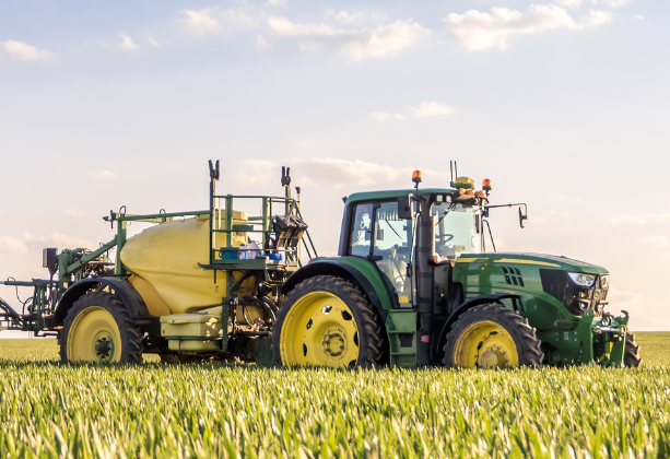


    Defining Automatic Rate Control on Sprayers

    Automatic rate control refers to the ability of a sprayer to change the volume of fluid dispersed in a given amount of time to maintain a preset application rate without manual adjustments by the operator. This is accomplished via a combination of specific components working together. The operator sets their parameters, and these sprayer controls are then able to accurately deliver the desired result. 

    Automatic rate control offers several advantages over less sophisticated manual sprayer controls such as having significant improvement in your accuracy, efficiency, and cost-effectiveness of agricultural spraying operations. 


    Advantages of Automatic Sprayer Rate Control

    • Accuracy: Real-time adjustments for precise application, reducing human error and ensuring consistent coverage across varying speeds and terrain.
    • Efficiency: Minimizes over-application and under-application, optimizing the use of chemicals, fertilizers, and water.
    • Cost Savings: Reduces product wastage, lowering input costs by applying only the necessary amount of liquid over the target area.


    Pressure Versus Flow Meter Based Rate Control

    When discussing automated sprayer controls, it is important to note that the output or application rate of a sprayer can be managed in two distinct ways: pressure-based control and flowmeter-based control. In pressure-based systems, the sprayer’s application rate is controlled by monitoring and adjusting the system’s pressure with a regulating valve to increase or decrease the sprayer's output.

    In flow meter-based systems, the application rate is controlled by using a flowmeter to precisely measure the amount of liquid flowing through the system and using a valve or pump speed control to adjust the volume of liquid.

    Both methods can be used to automate a sprayer's output, but the necessary components and overall system are slightly different. At Dultmeier Sales, we tend to see flow meter-based control systems more often, and that is what we will focus on in this article. 


    Key Components of an Automatic Rate Control System

    There are many ways one can go about setting up a sprayer. Pressure sensors, agitation, tank monitors, air clean out, boom section valves, etc. These pieces add valuable features, but they are not all required for the sprayer to monitor and maintain a rate automatically. The base components that are needed for a flow meter-based automatic rate control system include a rate controller, flow meter, regulating valve, and speed/GPS sensor

    There are several variations of each component in terms of size, design, and brand, but they all work together in the same basic way. As the sprayer moves through the field, the speed sensor continuously updates the rate controller on the ground speed. The flow meter measures the actual liquid flow, and the rate controller compares this with the desired rate. If adjustments are needed, the controller instructs the pump or regulating valve to modify flow.


    Automatic Rate Control System Setup

    Each piece needed to automatically adjust your sprayer’s rate is important, but it is also just as important to install them in the correct way. In the image below, you can see a basic sprayer plumbing layout for a flow meter-based automatic rate control: 
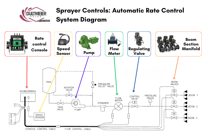


    The control console will require a wiring harness that connects to the flow meter (or PWM valve/motor - more on this below), a regulating valve, and the boom section valves (if applicable). The GPS radar or speed sensor will also connect to the rate control console. 

    In the diagram, the flow meter is installed after the pump and prior to the regulating valve. This flow meter must be on the pressure or discharge side and the plumbing after it must be solely supplying the boom. This way it can tell the control console the exact rate of fluid being applied. 

    The regulating valve could be installed before the flow meter, but then the adjustments from the regulating valve would disturb the steady flow of liquid and potentially cause inaccurate readings from the meter. 

    Another option is to install the regulating valve in a return line to the sprayer tank. Again, there are several different ways to accomplish this, but the basic setup would look like this: 
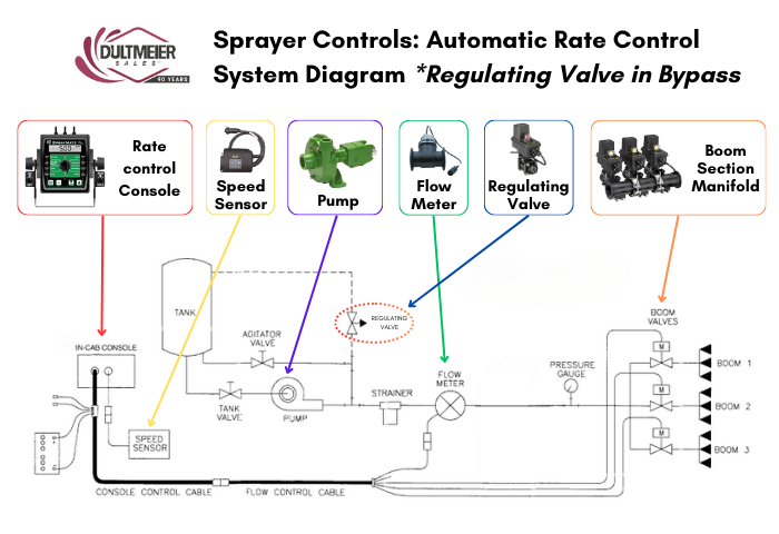


    Although boom section valves are not necessary for auto rate control, rate control consoles often come with boom section switches to control multiple valves. If you have a GPS-guided/mapping system, the section valves can be opened/closed automatically by the console.  

    As referenced earlier, there are several different types of each component, size, types, brands, etc. Different brands can typically communicate with one another, you just need to ensure you have the proper wire harness and adapters. 

    If you are unsure about a valve, flow meter, or other parts working together, give us a call. We can help with Raven, Micro-Trak, and TeeJet systems for agriculture, de-ice, and several other types of sprayers. 

    Now let’s look at each piece of the puzzle a little closer.

    Rate Controller

    The rate controller is the "brain" of the entire system. It contains the electrical programming to process the data it receives from the flow meter and speed sensor and uses this information to adjust the flow by controlling the regulating valve or PWM (Pulse Width Modulation) valve or motor depending on the setup.

    To do this the rate controller needs to know certain information. The operator supplies it with the desired application rate and the spacing of the nozzle on the spray boom. To make the proper adjustments as the speed changes, the controller also must be able to know the travel speed of the sprayer and the flow rate of liquid through the system. This is where the speed sensor/GPS sensor and flow meter come into play.


    Recommended Rate Controllers:

    Teejet 845: The 845 sprayer control is an easy rate controller to program and features five boom section valve switches, PWM pump control, and options for variable rate control. 

    Micro-Trak Spray Mate: The SprayMate II is a compact controller that offers lots of operator-minded/user-friendly features to control multiple rates on the go. Micro-Trak’s SprayMate Plus offers both flow- and pressure-based control as well as PWM compatibility.

    Raven 450: SCS 450 rate controllers provide feedback on a variety of spraying information such as total volume applied, total area covered, distance traveled, area covered per hour, and more. Works with regulating valves and PWM systems. Integrates seamlessly with other Raven products.


    Flow Meter

    Flow meters are a fundamental component in any automatic rate control system. A flow meter's function is to monitor the flow rate of the liquid being sprayed. It measures the gallons per minute (GPM) flowing through the system and sends this information to the rate controller.

    There are different sizes of flow meters available, and the size corresponds to the flow range that the meter can accurately read. For example, a Raven RFM60P will register flows of 1-55 gallons per minute. This model is a fairly common flow meter for agricultural sprayers. 

    View Flow Meter Options Here


    Pressure Sensors

    In a pressure-based control system, a pressure transducer or sensor would be used to monitor the PSI within the sprayer. The rate controller would make any appropriate adjustments based on this reading rather than a flow meter. Pressure sensors can still be used with a flow meter-based system to monitor the pressure in the system, while the flow meter is used to monitor the rate.


    Speed Sensor / GPS

    Tracking the sprayer's ground speed is another necessary factor in auto rate control. GPS radar receivers register and deliver this data to the rate controller. This input is necessary because the flow rate alone is insufficient for precise control; you also need to know how fast the sprayer travels. Faster travel speeds require a higher volume of liquid output to maintain the same rate. Likewise, a lower volume is needed at slower speeds.  

    Most speed sensors use GPS to measure the speed; however, some options do not require a GPS signal and instead measure the rotation of a shaft/wheel. These can work great if you want to avoid investing in a GPS antenna/receiver or are concerned about getting a reliable GPS signal in your area.  

    Speed Sensors Options:


    Regulating Valves

    The regulating valve is the last piece of the puzzle. The rate controller uses the inputs from the flow meter and speed sensor to adjust the regulating valve according to the parameters you set in the controller.

    In most scenarios, the regulating valve is an electric ball or butterfly valve. The electric motor rotates the ball or disc inside to increase or decrease the flow rate as needed. 

    View Regulating Valve Options Here


    PWM Valves/Motors

    Some automatic rate control systems don’t use a regulating valve, and the flow is instead controlled with PWM (Pulse Width Modulation). In these PWM systems, the rate controller adjusts the speed of a pump motor to increase or decrease the flow rate. 
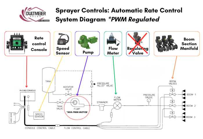


    There are centrifugal, piston, and diaphragm pumps that come equipped with PWM-controlled hydraulic motors. With these types of pumps, the rate controller cable that would normally attach to your regulating valve instead connects to the PWM hydraulic motor: 

    You can also buy a PWM hydraulic valve or PWM valve/motor combo to add to an existing pump:


    Key Takeaways

    Although there are several ways to build your system, adding automatic rate control to your sprayer doesn’t have to be complicated. There are simple and affordable options that will give you the efficient and effective control that you desire, and which best suit your unique application needs. This article will help ensure that you have the right set of components and understand the basics of how those individual components work within the larger system. If you need any assistance, we here at Dultmeier Sales are happy to help you get your automatic rate control system up and running. 


    If you need assistance setting up your sprayer, don’t hesitate to give us a call
    .

    Spot Free Woes: Troubleshooting Guide for Car Wash RO Systems

    As a car wash owner, you know how frustrating those pesky water spots can be-they're the bane of a perfect wash and can leave customers dissatisfied. Ensuring your RO (Reverse Osmosis) system is functioning properly is crucial to delivering that spot-free shine every time.

    In this guide, we'll dive into the reasons behind Spot Free RO system failures and how to fix the issue, helping you maintain that flawless finish and keep your customers happy. Let's get started on troubleshooting!

    Common RO System Symptoms and What to Do About It

    When your RO system is not performing up to par, there could be several possible culprits. Let's look at some of the most common symptoms you might face, the possible root causes, and how to fix them.

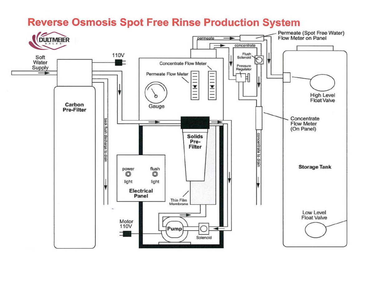
    RO spot free rinse production system diagram

    Symptom: Low Flow or No Water Production

    Possible Cause: Clogged Pre-Filter

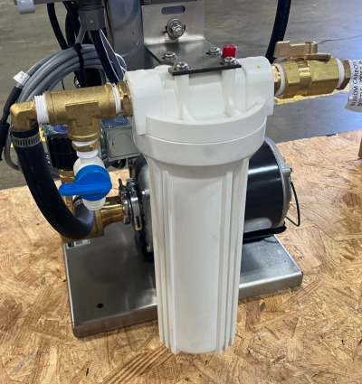
    Pre-filters in an RO system are designed to capture large particles, debris, and other contaminants before water reaches the RO membrane. Over time, these pre-filters can become clogged, reducing the system's flow rate and potentially causing a disruption in water production.


    RO spot free rinse pre-filter


    Solution: Inspect and replace pre-filters if necessary.  Check the TDS with a meter to see if the membrane is making acceptable water (learn more about using TDS meter here). Sometimes you can see debris on the incoming side of the membrane when it is removed. If there is no noticeable debris it can be restricted throughout the field of the wrap of the membrane resulting in little to no flow.

    Higher flow and higher TDS on the permeate side usually indicated a fouled or bursting membrane. Before replacing a membrane be sure the water softener is working properly, producing zero grain soft water. The softener brine tank should be cleaned periodically.


    Possible Cause: Low inlet water pressure

    For an RO system to function properly, it requires adequate inlet water pressure. If the water pressure is too low, the membrane will not be able to filter water effectively, leading to reduced flow or complete system shutdown.

    Solution: Make sure the water softener is flowing correctly and that the bypass valve is fully closed. Check all valves ahead of the unit to make sure no shut-off valves are closed or not fully opened.


    Possible Cause: Pump Failure

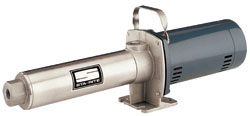
    The booster pump plays a crucial role in increasing water pressure to the RO membrane. If the pump fails, the system will not have sufficient pressure to produce water, leading to reduced flow or no production.

    Solution: Consult the MFG for troubleshooting help or Dultmeier sales.


    Possible Cause: RO System in Flush Mode

    Many Spot Free RO systems (like the Dultmeier DUSFR) are equipped with a flush mode, where water is run through the system to clean the membrane. During this cycle, water production will be reduced, and the system will appear to have low flow.

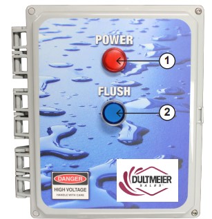
    Solution: Consult your manual to determine how to shut off the flush mode. If you have a Dultmeier RO system, it is equipped with an automatic flush mode. After 3 minutes the system should return to normal operation. If the system does not return to normal operation after this type, examine the flush valve for debris. You can consult the manual for more details on the flush valve location.


    Spot free RO system control panel


    Possible Cause: Incorrect Setting on the Pump Relief Valve.

    The pump relief valve controls the pressure within the system. If it is incorrectly set, it can cause either low or excessively high water pressure, both of which can impact water production.

    Solution: Consult the system manual to identify the proper relief valve setting and make any needed adjustments.


    Symptom: Clogged Membrane 

    Possible Cause: Carbon Not Flushed Properly

    The carbon filter in an RO system is designed to remove chlorine, sediments, and organic compounds before the water reaches the RO membrane. If the carbon filter is not flushed properly upon installation or after routine maintenance, carbon particles can pass through to the membrane, leading to clogging.

    Solution: Flush the carbon filter through a full cycle. Check the carbon filter for proper plumbing.


    Possible Cause: Organic or Inorganic Matter in Water Supply

    The incoming water supply can contain organic contaminants (such as bacteria, algae, or plant material) or inorganic materials (such as sand, rust, or other mineral particles) that are too large or difficult for the RO membrane to filter. Over time, these contaminants can accumulate on the membrane surface, clogging it and reducing its ability to filter water effectively.

    Solution: Have water tested before replacing the membrane.

    Managing your RO membranes is vital, for more information, you should read our guide on changing RO membranes


    Symptom: Increased RO Production, High TDS, or Decrease in PSI

    Possible Cause: Membrane installed upside down. 

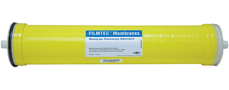
    The RO membrane must be installed in the correct orientation for water to pass through and filter properly. If the membrane is installed upside down, the flow of water is reversed, preventing the membrane from performing its intended function. This can result in poor water filtration, leading to high TDS levels and increased water production because the system isn't removing contaminants properly.

    Solution: Turn the Membrane in the opposite direction.

    reverse osmosis element/membrane

    Possible Cause: Chlorine in the RO system

    Chlorine is harmful to RO membranes. If chlorine is not filtered out properly by the carbon pre-filter, it can damage or degrade the RO membrane. This leads to poor water quality (high TDS) and often increased water production since the membrane is less effective at filtering contaminants.

    Solution: Inspect, and/or repair the carbon filter.


    Possible Cause: Ruptured Membrane

    A ruptured membrane can occur due to wear and tear, excessive pressure, or chemical damage (e.g., from chlorine). A ruptured membrane cannot properly filter out contaminants, leading to higher TDS levels and increased water production as the system allows more water to pass through without effective filtration.

    Solution: Shut off the system and remove the membrane from its housing. Inspect the membrane for visible damage, such as tears, holes, or a complete rupture. If the membrane is damaged, it must be replaced immediately. Install the new membrane, making sure it is properly seated in the housing and oriented correctly.


    Did you know Dultmeier Sales keeps a variety of RO membranes and Housings In stock? Be sure to check out the available options for pre-filters, chlorine carbon filters, RO filters, RO membranes, and sediment cartridge filters:


    Reverse Osmosis Systems and Filters


    Symptom: Water Flowing to RO Storage Tank When Unit is Not in Production

    Possible Cause: Debris in inlet solenoid or defective inlet solenoid

    The inlet solenoid valve controls the flow of water into the RO system. If debris clogs the solenoid or if the solenoid is defective, it may not close properly, allowing water to flow into the system even when it should not be producing. This could result in a constant flow of water to the tank, even when the system is not actively producing permeate (filtered water).

    Solution: Remove the inlet solenoid valve according to your system's manual. Carefully inspect it for any signs of debris, dirt, or mineral buildup that may prevent it from closing properly. Use a soft brush or cloth to clean any debris or buildup around the valve. Ensure that the valve can open and close smoothly after cleaning.

    After cleaning, reconnect the solenoid and turn the system back on. Listen for any clicking noises when the system is supposed to open or close the valve. If the valve is not working as expected, it may be defective. If cleaning does not resolve the issue or if the solenoid shows signs of wear, malfunction, or failure, replace the inlet solenoid with a compatible part for your RO system.


    Symptom: Noisy Pump/ Underperforming Pump

    Possible Cause: Inlet is obstructed, or restricted.

    The pump relies on a consistent and unobstructed flow of water to function efficiently. If the inlet is blocked or restricted by debris, sediment buildup, or a clogged pre-filter, the pump has to work harder to move water through the system. This can result in unusual noises and reduced water flow, leading to underperformance.

    Solution: Remove the prefilter and inspect it for signs of blockage or clogging. Replace the prefilter if it is dirty or past its recommended service life. Inspect the inlet lines for blockages or restrictions. These lines can accumulate sediment or scale, which may impede water flow. Clean the inlet lines by flushing them with clean water. If the lines are severely clogged, they may need to be replaced.


    Possible Cause: Coupling, mounting bolts are loose. 

    A pump with loose coupling or mounting bolts can cause excessive vibration and noise. Loose bolts can lead to pump wear and potential damage to the housing or connections.

    Solution: Check Coupling Alignment: Inspect the coupling for any signs of wear or misalignment. If the coupling is visibly worn or damaged, replace it. Ensure all bolts securing the pump to the frame or motor are tightly fastened. Avoid over-tightening the bolts, as this could cause damage to the components. Ensure the pump remains securely mounted but allows for the necessary vibration isolation (if designed that way).

    If the pump and motor are not properly aligned, this can cause additional strain on the components and lead to noise. Adjust the pump's position so that it is perfectly aligned with the motor.


    You Can Find RO System Booster Pumps and Repair Parts Here


    Possible Cause: The water source is off or not fully open

    If the water source is not fully turned on or if the water valve is only partially open, the pump may be starved of water. This can cause cavitation inside the pump, which can lead to inefficiency and damage to the pump over time.

    Solution: Ensure that the water source is fully turned on. Sometimes, water valves may appear open but are only partially allowing water through. Double-check to make sure the valve is fully open. Trace the water supply lines leading to the pump and ensure there are no blockages or kinks that might be restricting water flow. This includes valves, hoses, and any filtration units before the pump.


    RO System Maintenance & Troubleshooting Tips

    • Always disconnect the power before attempting any troubleshooting to avoid electric shock.
    • Regularly flush the system to maintain optimal membrane performance and avoid clogs.
    • Replace parts proactively based on the wear or inefficiency noted during daily inspections.
    • Check the prefilter monthly: Replace after approximately 200 gallons or more frequently if needed.
    • Inspect daily for leaks, ensure drain hoses are secure, and check pressure and flow gauges for abnormalities.
    • Test for chlorine using the service valve and a test strip to avoid chlorine damage to the membrane.
    • Monitor TDS levels: The permeate water should have a TDS reading between 0 and 40 ppm. If TDS is above 40 ppm, then the membrane should be replaced. Learn more in our guide on how to test and how often to change RO membranes
    • Inspect the float switch regularly to ensure proper operation.


    Keys to Remember

    Maintaining a spot-free RO system requires regular inspection and cleaning of filters, membranes, and solenoids, ensuring proper water pressure and flow, and securing pump components. Addressing issues like clogged filters, misaligned parts, and proper valve settings prevents noise, low production, and high TDS. Routine maintenance ensures optimal system performance and extends the lifespan of your equipment.

    Dultmeier sales car wash tech team has experience with Spot Free RO systems. Be sure to contact us for more help!