Search
Call for Live Order Assistance & Technical Support (7:30am-5pm CST)
All Categories
    Menu Close
    RSS

    Blog posts tagged with 'car-wash-truck-wash'

    How Often Should You Change Your RO Membranes? A Complete Guide

    Maintaining your RO system properly not only ensures spot-free results in your car wash but also extends the lifespan of your equipment. One of the most important aspects is replacing the RO membrane. This guide will cover how often you should change your RO membranes, what signs indicate it’s time for a replacement, and the tools and equipment you’ll need to perform this task effectively. Let’s dive in.


    Understanding RO Membranes and Their Importance

    An RO membrane is a core component of your RO system, responsible for filtering out dissolved solids, contaminants, and other impurities from the water. Over time, the membrane's ability to filter water diminishes due to several factors, primarily scaling and general wear and tear, making regular replacement necessary to maintain optimal water quality.

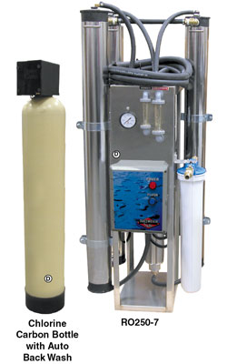
    Chlorine filters are essential to prevent chlorine from entering the membranes, as chlorine will cause rapid damage and failure. Additionally, a water softener is typically required to reduce water hardness to zero before it enters the membranes. When newly installed, the membranes take TDS down to zero.


    How Often Should You Change Your RO Membranes?

    Generally, RO membranes can last up to about 1 to 5 years, but the exact lifespan depends more on system usage and water quality than on time alone. Rather than focusing on a specific timeframe, it’s best to monitor the Total Dissolved Solids (TDS) level in the water your system produces. When TDS levels start to rise, it indicates that the membrane is less effective and may need replacing. This approach helps you avoid unnecessary changes while ensuring optimal water quality.

    Here are some key considerations to help you determine the optimal time to replace your membranes:

    Water Quality and Pre-Treatment

    • The quality of your incoming water greatly affects the lifespan of the membrane. High levels of water hardness, iron, or chlorine will greatly affect membrane life. If your water supply has high levels of these contaminants, you will likely need to replace membranes more frequently.
    • Pre-treatment options, such as sediment filters, carbon filters, and water softeners are very important for extending membrane life by reducing the burden on the RO membrane. 

    You can contact our sales team for help selecting pre-treatment options.

    System Usage

    • The more frequently your RO system is used, the faster the membrane will become filled with contaminants, and performance will go down. For car wash operations with heavy daily usage, you may need to replace the membrane more frequently.
    • In contrast, for systems used less frequently or with lower output, a membrane will last much longer.

    Regular Monitoring and Maintenance

    Performing weekly TDS checks is a key to monitoring the condition of your RO membrane. A handheld TDS meter can help you measure the TDS levels in the permeate (filtered water). If TDS readings exceed 40 ppm, it’s time to replace the membrane, as spotting generally occurs at this reading and above.

    Regular maintenance and monitoring can help catch issues early, preventing costly replacements and downtime. Cleaning the inlet filter and solenoid can prevent strain on the membrane. Your water softener should also be backflushed periodically. Many systems have an automatic backflush feature that cleans the filter media by flushing out accumulated contaminants, dirt, and debris, helping maintain the filter’s efficiency and lifespan.


    Testing the TDS with a Handheld Meter

    Step-by-Step Instructions for Testing TDS with a Handheld Meter

    1. Prepare a Clean Sample Container:
      • Collect a cup or use the cap of the meter to hold your water sample.
      • Rinse the container thoroughly to ensure it is free of any contaminants.
    2. Collect the Water Sample:
      • Use the container to collect a sample of the permeate (filtered water) from your RO (Reverse Osmosis) system.
    3. Turn on the TDS Meter:
      • Remove the cap from the TDS meter.
      • Press the ON button to activate the meter.
    4. Insert the Meter into the Sample:
      • Place the TDS meter into the water sample up to the “ribbed” section on the meter for an accurate test (see image below).
    5. Swirl the Meter:
      • Gently swirl the TDS meter in the water for about 10 seconds to ensure the water flows consistently around the sensor.
    6. Hold the Reading:
      • Press the HOLD button on the meter to lock in the reading. This will allow you to remove the meter from the water without losing the result.
    7. Read and Record the TDS Level:
      • Check the TDS level displayed on the screen in parts per million (ppm).
      • The meter will hold this reading for approximately 20 seconds, giving you time to record the result.
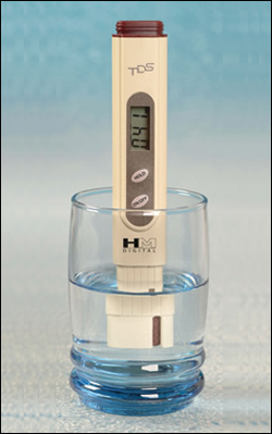
     

    Dultmeier Item #HMTDS4


    Signs It’s Time to Replace Your RO Membrane

    Apart from monitoring TDS, there are additional signs that indicate it may be time for a new membrane:

    • High TDS Levels: If TDS readings start to increase rapidly or are above 40 ppm despite cleaning or flushing the system, this is a clear indicator that the membrane is no longer effective.
    • Decreased Water Production: A significant reduction in the system’s output or water flow could mean that the membrane is fouling or needing service.
    • Visible Spotting on Vehicles: For car wash systems, if you notice water spots on vehicles after washing, this suggests that the membrane isn't producing spot-free water.
    • Increased RO System Noise: An underperforming pump or noisy operation could indicate that the membrane is placing too much strain on the system.

    RO systems are complex and you can find more details in our guide to RO system troubleshooting.


    Recommended Tools and Equipment for RO System Maintenance

    To keep your RO system running smoothly, equip yourself with the following tools and replacement parts:

    Replacement RO Membranes

    Choose the right membrane based on your system’s specifications. Dultmeier offers a selection of RO membranes from several different manufacturers and systems.   

    TDS Meters

    Handheld TDS meters are essential for regular monitoring. You can use these to quickly check if your membrane is maintaining water at the appropriate quality standards.

    Pre-Treatment Filters


    Best Practices for Extending RO Membrane Life

    Perform Regular Maintenance

    Schedule routine checks on the prefilter, membrane, pump, softener, and carbon bottle. Replacing prefilters regularly will reduce the load on the membrane, ensuring it lasts longer.

    Flush the System Periodically

    Run a flush cycle to remove accumulated debris and scale from the membrane. This should be done according to your system's maintenance schedule or as needed based on water quality.

    Dultmeier offers RO systems with automatic flush mode, you can learn more about these systems here.  

    Invest in High-Quality Pre-Treatment Solutions

    Adding carbon filters, sediment filters, or water softeners will help protect your membrane from harmful contaminants and extend its service life.

    Monitor Water Quality Weekly

    Using TDS meters for regular monitoring helps you detect when the membrane begins to deteriorate. By staying ahead of TDS increases, you can replace the membrane before it causes major issues.


    Conclusion

    Changing your RO membrane every 1 to 5 years is a general guideline, but regular monitoring and maintenance play a critical role in determining the actual replacement schedule. By keeping a close eye on TDS levels, addressing any performance drops, and using quality replacement parts and pre-treatment equipment, you can maximize the efficiency and lifespan of your RO system.

    Spot Free Woes: Troubleshooting Guide for Car Wash RO Systems

    As a car wash owner, you know how frustrating those pesky water spots can be-they're the bane of a perfect wash and can leave customers dissatisfied. Ensuring your RO (Reverse Osmosis) system is functioning properly is crucial to delivering that spot-free shine every time.

    In this guide, we'll dive into the reasons behind Spot Free RO system failures and how to fix the issue, helping you maintain that flawless finish and keep your customers happy. Let's get started on troubleshooting!

    Common RO System Symptoms and What to Do About It

    When your RO system is not performing up to par, there could be several possible culprits. Let's look at some of the most common symptoms you might face, the possible root causes, and how to fix them.

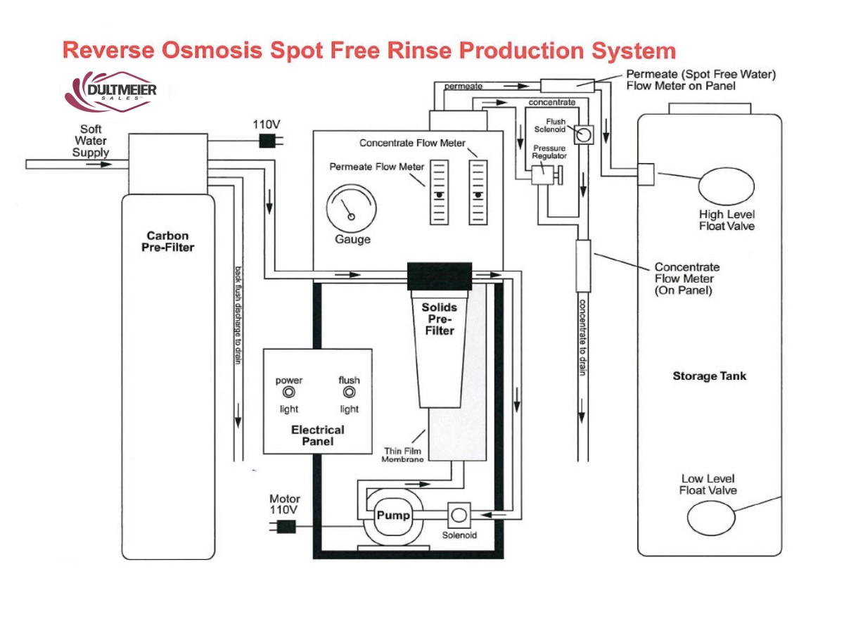
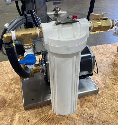
    RO spot free rinse production system diagram

    Symptom: Low Flow or No Water Production

    Possible Cause: Clogged Pre-Filter

    Pre-filters in an RO system are designed to capture large particles, debris, and other contaminants before water reaches the RO membrane. Over time, these pre-filters can become clogged, reducing the system's flow rate and potentially causing a disruption in water production.


    RO spot free rinse pre-filter


    Solution: Inspect and replace pre-filters if necessary.  Check the TDS with a meter to see if the membrane is making acceptable water (learn more about using TDS meter here). Sometimes you can see debris on the incoming side of the membrane when it is removed. If there is no noticeable debris it can be restricted throughout the field of the wrap of the membrane resulting in little to no flow.

    Higher flow and higher TDS on the permeate side usually indicated a fouled or bursting membrane. Before replacing a membrane be sure the water softener is working properly, producing zero grain soft water. The softener brine tank should be cleaned periodically.


    Possible Cause: Low inlet water pressure

    For an RO system to function properly, it requires adequate inlet water pressure. If the water pressure is too low, the membrane will not be able to filter water effectively, leading to reduced flow or complete system shutdown.

    Solution: Make sure the water softener is flowing correctly and that the bypass valve is fully closed. Check all valves ahead of the unit to make sure no shut-off valves are closed or not fully opened.


    Possible Cause: Pump Failure

    The booster pump plays a crucial role in increasing water pressure to the RO membrane. If the pump fails, the system will not have sufficient pressure to produce water, leading to reduced flow or no production.

    Solution: Consult the MFG for troubleshooting help or Dultmeier sales.


    Possible Cause: RO System in Flush Mode

    Many Spot Free RO systems (like the Dultmeier DUSFR) are equipped with a flush mode, where water is run through the system to clean the membrane. During this cycle, water production will be reduced, and the system will appear to have low flow.

    Solution: Consult your manual to determine how to shut off the flush mode. If you have a Dultmeier RO system, it is equipped with an automatic flush mode. After 3 minutes the system should return to normal operation. If the system does not return to normal operation after this type, examine the flush valve for debris. You can consult the manual for more details on the flush valve location.


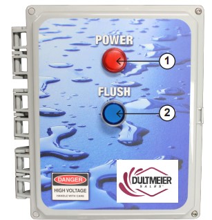
    Spot free RO system control panel


    Possible Cause: Incorrect Setting on the Pump Relief Valve.

    The pump relief valve controls the pressure within the system. If it is incorrectly set, it can cause either low or excessively high water pressure, both of which can impact water production.

    Solution: Consult the system manual to identify the proper relief valve setting and make any needed adjustments.


    Symptom: Clogged Membrane 

    Possible Cause: Carbon Not Flushed Properly

    The carbon filter in an RO system is designed to remove chlorine, sediments, and organic compounds before the water reaches the RO membrane. If the carbon filter is not flushed properly upon installation or after routine maintenance, carbon particles can pass through to the membrane, leading to clogging.

    Solution: Flush the carbon filter through a full cycle. Check the carbon filter for proper plumbing.


    Possible Cause: Organic or Inorganic Matter in Water Supply

    The incoming water supply can contain organic contaminants (such as bacteria, algae, or plant material) or inorganic materials (such as sand, rust, or other mineral particles) that are too large or difficult for the RO membrane to filter. Over time, these contaminants can accumulate on the membrane surface, clogging it and reducing its ability to filter water effectively.

    Solution: Have water tested before replacing the membrane.

    Managing your RO membranes is vital, for more information, you should read our guide on changing RO membranes


    Symptom: Increased RO Production, High TDS, or Decrease in PSI

    Possible Cause: Membrane installed upside down. 

    The RO membrane must be installed in the correct orientation for water to pass through and filter properly. If the membrane is installed upside down, the flow of water is reversed, preventing the membrane from performing its intended function. This can result in poor water filtration, leading to high TDS levels and increased water production because the system isn't removing contaminants properly.

    Solution: Turn the Membrane in the opposite direction.

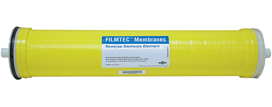
    reverse osmosis element/membrane

    Possible Cause: Chlorine in the RO system

    Chlorine is harmful to RO membranes. If chlorine is not filtered out properly by the carbon pre-filter, it can damage or degrade the RO membrane. This leads to poor water quality (high TDS) and often increased water production since the membrane is less effective at filtering contaminants.

    Solution: Inspect, and/or repair the carbon filter.


    Possible Cause: Ruptured Membrane

    A ruptured membrane can occur due to wear and tear, excessive pressure, or chemical damage (e.g., from chlorine). A ruptured membrane cannot properly filter out contaminants, leading to higher TDS levels and increased water production as the system allows more water to pass through without effective filtration.

    Solution: Shut off the system and remove the membrane from its housing. Inspect the membrane for visible damage, such as tears, holes, or a complete rupture. If the membrane is damaged, it must be replaced immediately. Install the new membrane, making sure it is properly seated in the housing and oriented correctly.


    Did you know Dultmeier Sales keeps a variety of RO membranes and Housings In stock? Be sure to check out the available options for pre-filters, chlorine carbon filters, RO filters, RO membranes, and sediment cartridge filters:


    Reverse Osmosis Systems and Filters


    Symptom: Water Flowing to RO Storage Tank When Unit is Not in Production

    Possible Cause: Debris in inlet solenoid or defective inlet solenoid

    The inlet solenoid valve controls the flow of water into the RO system. If debris clogs the solenoid or if the solenoid is defective, it may not close properly, allowing water to flow into the system even when it should not be producing. This could result in a constant flow of water to the tank, even when the system is not actively producing permeate (filtered water).

    Solution: Remove the inlet solenoid valve according to your system's manual. Carefully inspect it for any signs of debris, dirt, or mineral buildup that may prevent it from closing properly. Use a soft brush or cloth to clean any debris or buildup around the valve. Ensure that the valve can open and close smoothly after cleaning.

    After cleaning, reconnect the solenoid and turn the system back on. Listen for any clicking noises when the system is supposed to open or close the valve. If the valve is not working as expected, it may be defective. If cleaning does not resolve the issue or if the solenoid shows signs of wear, malfunction, or failure, replace the inlet solenoid with a compatible part for your RO system.
     

    Symptom: Noisy Pump/ Underperforming Pump

    Possible Cause: Inlet is obstructed, or restricted.

    The pump relies on a consistent and unobstructed flow of water to function efficiently. If the inlet is blocked or restricted by debris, sediment buildup, or a clogged pre-filter, the pump has to work harder to move water through the system. This can result in unusual noises and reduced water flow, leading to underperformance.
    Solution: Remove the prefilter and inspect it for signs of blockage or clogging. Replace the prefilter if it is dirty or past its recommended service life. Inspect the inlet lines for blockages or restrictions. These lines can accumulate sediment or scale, which may impede water flow. Clean the inlet lines by flushing them with clean water. If the lines are severely clogged, they may need to be replaced.


    Possible Cause: Coupling, mounting bolts are loose. 

    A pump with loose coupling or mounting bolts can cause excessive vibration and noise. Loose bolts can lead to pump wear and potential damage to the housing or connections.

    Solution: Check Coupling Alignment: Inspect the coupling for any signs of wear or misalignment. If the coupling is visibly worn or damaged, replace it. Ensure all bolts securing the pump to the frame or motor are tightly fastened. Avoid over-tightening the bolts, as this could cause damage to the components. Ensure the pump remains securely mounted but allows for the necessary vibration isolation (if designed that way).

    If the pump and motor are not properly aligned, this can cause additional strain on the components and lead to noise. Adjust the pump's position so that it is perfectly aligned with the motor.


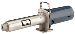
    You Can Find RO System Booster Pumps and Repair Parts Here


    Possible Cause: The water source is off or not fully open

    If the water source is not fully turned on or if the water valve is only partially open, the pump may be starved of water. This can cause cavitation inside the pump, which can lead to inefficiency and damage to the pump over time.

    Solution: Ensure that the water source is fully turned on. Sometimes, water valves may appear open but are only partially allowing water through. Double-check to make sure the valve is fully open. Trace the water supply lines leading to the pump and ensure there are no blockages or kinks that might be restricting water flow. This includes valves, hoses, and any filtration units before the pump.


    RO System Maintenance & Troubleshooting Tips

    • Always disconnect the power before attempting any troubleshooting to avoid electric shock.
    • Regularly flush the system to maintain optimal membrane performance and avoid clogs.
    • Replace parts proactively based on the wear or inefficiency noted during daily inspections.
    • Check the prefilter monthly: Replace after approximately 200 gallons or more frequently if needed.
    • Inspect daily for leaks, ensure drain hoses are secure, and check pressure and flow gauges for abnormalities.
    • Test for chlorine using the service valve and a test strip to avoid chlorine damage to the membrane.
    • Monitor TDS levels: The permeate water should have a TDS reading between 0 and 40 ppm. If TDS is above 40 ppm, then the membrane should be replaced. Learn more in our guide on how to test and how often to change RO membranes
    • Inspect the float switch regularly to ensure proper operation.


    Keys to Remember

    Maintaining a spot-free RO system requires regular inspection and cleaning of filters, membranes, and solenoids, ensuring proper water pressure and flow, and securing pump components. Addressing issues like clogged filters, misaligned parts, and proper valve settings prevents noise, low production, and high TDS. Routine maintenance ensures optimal system performance and extends the lifespan of your equipment.

    Dultmeier sales car wash tech team has experience with Spot Free RO systems. Be sure to contact us for more help!

    (0) Sizing a Pressure Tank - Your Step-by-Step Guide

    Pressure tanks are used in a variety of applications, but a common usage is system efficiency.  For example, one reason someone might install a pressure tank in a plumbing system would be to keep the pump from constantly running.  In doing so, the pressure-regulating tank increases the longevity of the pump/motor and reduces maintenance and down time - ultimately resulting in lower operating costs.  Let's dive into a step-by-step how to of sizing a pressure tank.  


    Info You NEED to KNOW Before Starting

    Before beginning the process of sizing a tank, there are a few important important input data points to know in order to properly size a pressure tank:

    1. Flow Rate
    2. Cut-in/Cut-out Pressure
    3. Target Run Time

    A general rule of thumb, that most manufacturers suggest, is a run time of less than one minute if the horsepower is less than 1HP.  If the motor is over 1HP, then a good guideline to follow, is a run-time of 2 minutes or more.  Always confirm this, with your tank manufacturer of choice, as guidelines can vary.


    General Rule of Thumb for Sizing a Pressure Tank

    Generally, as a rule of thumb, one can follow these guidelines when sizing a pressure tank:

    1. 0-10 GPM: 1 gallon of drawdown per 1 GPM of flow
    2. 10-20 GPM: 1.5 gallons of drawdown per 1 GPM of flow
    3. 20 GPM+: 2 gallons of drawdown per 1 GPM of flow

    Drawdown can be defined as the amount of volume loss in the tank as the plumbing system "draws" off this pent up pressure. After all, the purpose of a pressure tank is to maintain pressure in a given system and give the pump a break. This way, the pump doesn't need to run constantly to remain at system pressure. While a pressure tank can appear costly up front, it will save in the long run. Less run time for the pump means less maintenance and less money in energy costs. 

    There are various orientations of pressure tanks and the most common are horizontal, inline, and vertical.  Be sure to determine which orientation works best for your plumbing setup.  

    Once we have identified our flow rate in gallons per minute (GPM), have identified our cut-in/cut-out pressure, and confirmed our target run time - we must determine what cut-in/cut-out pressure we want to set the system at.  


    Pressure Tank Sizing Explained

    An important equation to remember when sizing a pressure tank is below:


    Flow Rate X Run Time = Tank Draw Down Capacity


    Example: 

    Let's say we have a pump that produces 5 GPM and is ran by a Âľ HP motor.  Since I'm operating a motor that is less than 1 HP, we are going to assume that "ABC Manufacturer" recommends a 1-minute runtime.  We want to design this system to cut-in (turn on) at 40psi and cut-out (turn off) at 60psi.  

    5 (Flowrate) X 1 (Runtime) = 5 gallons of Draw Down (at 40/60PSI)

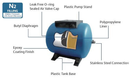
    So, I will need to select a tank that allows for 5 gallons of draw down at a pressure setting of 40PSI cut-in and 60PSI cut-out.  If I need a vertical tank, I could select a WOMAX-220.  If my plumbing layout would accommodate a horizontal tank better, I could select a WOMAXH-220.  This would give me approximately 3.5 minutes of run time before the pump would cycle back on. Horizontal pressure tanks have a plastic pump stand so you can maximize space when designing a plumbing system. This is certainly a nice feature when working in confined spaces where space is at a premium. 


    Relationship Between Pressure & Tank Size

    An important thing to remember, the higher the operating pressure - the larger the tank must be. Pressure and tank size have a direct correlation - as one increases, so does the other.  The higher the pressure setting, the less the drawdown is and thus, the need for larger tank capacity.  


    Wilo Pumps Logo


    After we have these three points determined, we can then proceed with sizing a pressure tank.  Pressure settings are another important factor with any plumbing system.  The most common pressure settings are 30/50; 40/60; 50/70.  Most manufacturers will have a pressure tank sizing chart that will allow viewers to quickly size a tank's drawdown based upon their system's pressure settings. 

    We can supply you with this information on the Wilo MaxAir® product line if you want to get into the details. Just give us a ring or visit www.dultmeier.com 24/7. Here is a drawing of a Wilo MaxAir® horizontal tank that outlines some features which set this product line apart from the rest of the pack and really make it one of the top line products in the marketplace. 


    Cutaway of Wilo MaxAir Horizontal Pressure Tank

    Cutaway of Wilo MaxAir Horizontal Pressure Tank


    You can view the full offering of Wilo MaxAir® Pressure Tanks Right Here on dultmeier.com. As always, should you have further questions about pressure tank sizing or other applications - don't hesitate to contact us.  That's what we are here for.  Your Experts in Delivering Fluid Handling Solutions - We Know Flow!

    (0) Pulley & Sheave Sizing - All Types of Pump Motors

    We commonly receive the call to help assist in properly sizing pulleys and sheaves for pump applications.  Generally, this is in high pressure wash applications but we also run into a fair amount of agricultural applications where this knowledge can be leveraged.  Pulleys or "sheaves" are commonly used for connecting pumps to motors or engines via drive belts.  Most pulleys are cast iron or aluminum construction and are offered in either fixed-bore or tapered bushing styles.

    Why is it Necessary to Size Pulleys for Each Application?

    For proper operation of any brand or pump type, it is critical to size pulleys and sheaves, correctly, in order to maintain correct RPM, (revolutions per minute)RPM speed is what determines the pump output flow rate - in gallons per minute, liters per minute, etc.

    Incorrect pump RPM will adversely affect the pump performance.  If the pump is turning too slow - it will not give full performance.  Conversely, if the pump is turning too fast, it could cause premature mechanical failures (i.e. valve wear or elastomer failure).

    Therefore, it is absolutely critical to ensure correct pulley sizing and analysis of the drive unit, (motor, engine, etc.) relative to the pump. For the sake of this discussion, we will assume standard electric motors at 1750 RPM and standard gas engines at 3400 RPM.  Do note, one must determine the rpm of their drive unit to be able to accurately calculate the pulley/sheave size.

    If you start with an incorrect figure for RPM - you will size your equipment incorrectly.  This could lead to shorter equipment lifespans and/or reduced output flow rates.  Thus, ultimately a less efficient system which equates to more down time and added cost of operation.  The scope of this post will be focused towards plunger pump applications.  We assemble many units using this method in Omaha, Nebraska.  Dultmeier Sales is proud to display the Built in the USA logo on our products.  Here are just a handful of the pulley-driven pump products that we offer.

    The Math of Pulley Sizing

    There are complicated formulas for determining pulley ratios but in generic, layman terms, simply divide the driven component (pump) by RPM, the driver component (motor or engine) rated by RPM to get the required ratio.  In the example below, the pump RPM is 1070, for full output, while the motor is 1750 RPM.

    Therefore, the ratio of the required pulleys would be:


    1070 (pump RPM) divided by 1750 (motor RPM) = .611


    This means the pulley ratio must be .611 to drive the pump correctly.  Hypothetically speaking, if we had a 4 inch pulley on the motor, we would require a 6.55" pulley on the pump.  That mathematical equation is as follows: 4" divided by .611 = 6.55"

    For the same pump, driven by a gas engine


    1070 (pump RPM) divided by 3400 (engine RPM) = .315 


    If the drive pulley on the engine is 4 inches in diameter, we need to calculate 4/.315 = 12.70.  This means that the pump pulley must be 12.70 inches, in diameter, to run the pump at 1070 rpm.  You can view a technical page from our catalog here - it will help to further explain the calculation process.

    Tapered Bushing vs. Fixed Shaft Bores

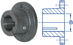
    Most pulleys, or sheaves, are designed with either fixed shaft bores or tapered bushing hubs.  Replaceable hubs fit the required motor or pump shaft size in either inch or mm sizes - depending on the application requirement.  These hubs come with bolts to attach them to the pulley, or sheave.


    Tapered Bushing


    Tapered style hubs simply fit into the pulley opening and then are tightened with two or three set screws, which draw the bushing and pulley together to make one assembly.  The pulleys are then attached to the driver (electric motor or gas engine) and driven components (pump).  The type of hub, H, SD, SH, etc. must match to a pulley with the same designation for proper fit.

    Therefore, make sure to identify what type of hub you have PRIOR to ordering.

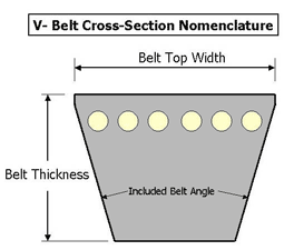
    Pulleys can be measured in a number of ways. Two of the most common methods are belt pitch and outside diameter (O.D.).  When using the, most common A/B, belt pitch method, one must identify both A belt pitch and B belt pitch.  This is the pitch diameter of the V-belt you are using, (A/B) is the measurement of how the belt fits into the groove of the pulley.


    pitch length


    A belts are not as wide as B belts and, therefore, sit lower in the pulley groove.  While this may seem as a minor detail - it absolutely affects the ratio measurement when properly sizing a pulley.

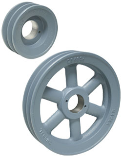
    Pulleys are available with different numbers of grooves. The number of grooves matches the number of belts that the pulley will accept.  A two groove pulley will accept two V-belts.  A single groove pulley will only accept one belt.

    Again as a general rule, (but not intended to use in every application) single groove pulleys with single belts can be used up to about 5 horsepower. Two groove belts can be used from 5-15 horsepower and three groove belts up to 25 horsepower.  Use this as a general guideline but always make sure you consult us if you are unsure of your application needs.


    Two Groove Sheaves

    Two Groove Pulleys


    For correct belt sizing, there are charts available that show the sum of the pulley diameters and the center distance they are apart, from each other.  We will be happy to supply you with one of those charts if you wish to have a copy.

    For instance, the sum of the two pulleys, in the above electric motor example is 4 inches + 6.5 inches = 10.5 inches.  The mathematical equation to figure this out is as follows:


    A - Pump Pulley O.D.    B - Motor Pulley O.D.


    Belt Size = [A*1.57] + [B*1.57] + [2*center distance between pulleys]


    76.5 = [4*1.57] + [6.5*1.57] + [2*30]


    If the pulleys are 30 inches apart, center to center, then the required belt length would be 77 inches.

    As the information above shows, there are many things involved in order to determine the correct pulleys required to drive your pumps correctly.  It is important to remember the larger the difference in pulley sizes, the larger the center distance required to maintain minimum contact with the smaller pulley.  We would be glad to help with any sizing for your specific applications.  Your Experts in Delivering Fluid Handling Solutions - We Know Flow!

    (0) From Nebraska to Maui - HDPE Can Be Found

    Maui - A Tropical Paradise

    We recently traveled to Maui, HI. The tropical paradise, virtually, has it all. From breathtaking beaches to arid, Sahara-like, geography, all the way to volcanic rock. In our travels, it's hard to find an industry in which the products we work with don't have a footprint or an impact. In this instance, our example is High-Density Polyethylene Pipe (HDPE). However, let's hold there and get to the island stuff first...

    Let's face it - when in Maui you could simply hang by the beach for the entirety of your stay and be able to soak in tons of the island life. However, for those more adventurous, I challenge you to explore all that this wonderful oasis has to offer. The Hana Highway is a unique adventure for those interested.

    If you plan to take the Road to Hana - make sure you get a Jeep. The mini-van made it but may or may not have required an alignment check after the trek. From hairpin turns along the tropical mountainside to sheer cliffs among the arid ocean walls of the Southeast side of Maui, Mother Nature will treat you and leave you stunned at the beautiful sights.

    The trip starts on the North shore of Maui and takes you past Jaws aka Pe'ahi - a popular surf destination on the island. From there one starts to climb - and climb fast. As you begin to make your way up Mt. Pu'unianiau you will wind your way through a seemingly endless amount of bridges, turns, and stunning views.


    Jaws - Maui


    Don't forget to stop and get your banana bread - it's a little island secret but we don't want to give that away here. Just make sure where to ask to stop along the Road to Hana and you will won't be sorry that you did. It is absolutely, hands down, the best banana bread in the world.

    Once you get through Hana you will begin making your way around the South side of the island - this is where the topography, as well as, geography begins to drastically change. What was once luscious jungle gives way to a Sahara-like climate.


    Bamboo along Pipiwai Trail Waimoku Falls Maui


    Along the South side of Maui, you will come across the southern end of the Halekala National Park. Within this national park, you will be able to walk to the Oheo Pools or the Waimoku falls along the Pipiwai Trail. While embarking on the trek of this trail (3-mile loop) you will make your way through a bamboo forest that is truly remarkable. The gentle breeze creates a "clicking" and "clanking" that reverberates throughout the forest.

    It was here, along the Pipiwai trail that we ran into our instructional scenario of the excursion. The park uses High-Density Polyethylene Pipe, or HDPE pipe for short, to transfer crystal clear water from the upper pools down to the recreational center hundreds of feet below, along the ocean shoreline.

    HDPE Uses - An Extremely Versatile Product

    We see HDPE pipe used from agricultural fertilizer applications to the petroleum industry in the oil fields and all the way to municipalities. The applications and uses for HDPE are endless. As the product is chemically compatible with a large number of solutions, it is a natural and obvious choice for many scenarios. Furthermore, it is an extremely economical option in comparison to steel or stainless steel pipe.

    The ease of installation makes HDPE another enticing choice - a fusion machine allows installers to, essentially, weld the pipe together in what's called a butt fusion - which is an extremely robust and sure connection. Below is a simple video that illustrates HDPE pipe and a butt fusion weld to a 45-degree elbow.


    While the majority of the applications, with which we are most familiar, are within the agricultural industry we do get into projects ranging from wash facilities to oil pipelines - and everything in between. If you have further questions about how HDPE pipe and/or fittings could be applied in your specific scenario don't hesitate to contact us. Here's to a wonderful 2018

    ~ Aloha Friends ~

    (0) How to Start a Car Wash Business

    Have you been pondering the idea of starting a car wash? Does the idea of passive income sound appealing? That's because it is. Do know that there is an extensive amount of upfront work and then there is the issue of ongoing maintenance. That being said, once you have an operational car wash up and running - you can consider it passive income.

    Everything You Need to Know About Starting a Car Wash Business

    The information below is a compilation of countless periodicals, customer surveys, and testimonials. At any point in the process of your new adventure, should you feel the need to ask about something in more detail don't ever hesitate to contact us. Let's dig into what you will need to do in order to properly align yourself to start a car wash.

    Car Wash Lot Selection

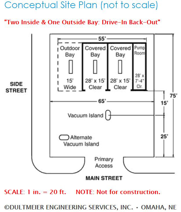
    A general rule to follow when sizing lot is that you will need a lot approximately 100 - 120 feet deep by a minimum of 75 feet wide - depending on the number of bays. Keep in mind a typical four bay self-serve car wash would need a lot 120 feet long by 100 feet wide - minimum. Another key attribute when selecting the ideal lot for your car wash is that it is accessible from both directions of traffic flow.

    For instance, if you select a lot that is on a one-way street it will negatively affect the volume your wash is capable of producing. The ideal traffic speed in the area of your lot selection should be around 40 miles per hour. This ensures that drivers have ample time to select your wash as their destination. The lot size and shape will determine if you design a "drive-in-back-out" or "drive-through" building.


    Free Catalog


    Data shows that income streams do favor the "drive-through" design. Lastly, when selecting your ideal location it is a good idea to target areas near residential neighborhoods, apartment complexes, or busy traffic routes. When determining if your ideal lot selection is a good fit for your business plan, you should consider the finances, as well.

    A safe rule to adhere to is that the cost of the property (monthly lease payment) should not exceed 15 - 20% of the gross monthly income of the wash. This ensures that you will not over-extend yourself, financially.


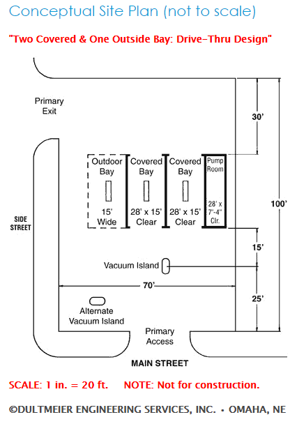
    Car Wash Site Plan


    Bay & Building Sizing

    An ideal bay is 16 feet wide by 28 feet long - these are the interior wall measurements. If you are planning a semi-truck bay make sure to account for internal wall measurements of 18 feet wide by 28 feet long. You can make a smaller bay work for trucks but why not just do it right from the start? The typical pump (equipment) room is 10 - 15 feet wide by 28 feet long (internal measurements).

    Furthermore, the typical bay height is 10 feet high for cars and 12 - 14 feet high for semi-trucks. Your lot size above will vary depending on what your overall wash purpose is (car vs. semi-truck) and the number of bays you intend to have. That's why we recommend determining the bay purpose and number of bays at the same time you are selecting your ideal lot location.

    Building Placement

    It's always best practice to consult local regulatory agencies to ensure your building is within code. That being said, your building should be situated on the lot to allow for one to two cars, minimum, to be parked behind each bay, waiting to wash. Vacuums should be placed in this area, as well, but should not be an impediment to the normal traffic flow into the bays. Another important concept to consider is that you ensure there are adequate drying and vacuuming areas.

    These areas should be out of the main traffic flow to avoid congestion. It is a good idea to allow for a southern exposure of your bays. This helps to reduce ice build-up in colder weather climates. Finally, make sure you plan for the "set-back" requirements on your building placement - this will vary with local ordinances.

    Inside vs. Outside Bays

    This aspect really does depend upon your market. Therefore, drive around and study the target market for the area which you have selected. That will give you a good idea of whether or not you need to have an outside bay or an inside bay. Washed located in a rural setting can be built with an open outside bay to accommodate trucks, trailers, and tractors. While this isn't required it can, and will, only allow for more traffic at your wash.


    How To Start a Car Wash Inside and Outside Bays


    Do keep in mind that an outside bay will bring in 50-60% of the revenue that an inside bay will. It is always better, from strictly a revenue standpoint, to enclose all bays and build one larger bay for semi-trucks - if you feel that your market will demand that. This larger bay can always be used for car traffic when an overflow bay is needed.


    Starting a Car Wash: Earnings & Costs

    Planning the financials for a self-serve car wash is essential for ensuring long-term profitability. Whether you’re considering opening a new location or optimizing an existing one, understanding projected revenue streams, costs, and features can help you make more informed business decisions.

    Revenue Projections

    Our experience tells us that it takes a population of about 1000-1500 people to support a single self-serve bay car wash. Therefore, one can conclude that a town of 5000 people will support a total of 5 self-serve bays - between ALL competitors. Given the current population level of the United States, the national average one can project roughly $2000/bay per month during peak traffic season(s). This is an estimated average - revenue can and will vary.

    The ideal number of vacuums to have is 1.5 vacuums per bay of service. Therefore, a three-bay wash should have four to five vacuums in an area of the lot that will not affect traffic flow. The national average per vacuum is approximately $200/vacuum per month. Again, revenue can and will vary.

    National averages of vending revenue are generally around the $400 per month range. This figure is based on offering at least four to five different vending products. Do keep in mind that revenue can be increased with multiple-product clear front vending machines.

    Operating Cost Projections

    One can expect that average operating costs are approximately 50% of gross revenue. This figure includes 13% for attendant labor, which may or may not be needed. Do note that lease payments, income tax, debt reduction or depreciation are not factored into this number. Furthermore, we must be clear that one should recognize these figures can and do vary from region to region.

    Options & Features

    A standard self-serve wash will offer hot wash/hot rinse in the winter and cold rinse in the summer. Additionally, hot or cold wax, foamy brush and spot-free rinse should be considered. Spot-Free rinse is an important feature. It increases revenue due to the fact that customers need to "buy" another cycle of time to get this feature. What does this mean? Double the income from each customer that decides to use this feature. Tire cleaner and pre-soak systems are also options that increase customer satisfaction and increase revenue.

    We highly recommend that instantaneous tankless water heaters be used in place of conventional water heaters. An instantaneous heater can reduce gas consumption by up to 40% in comparison to a conventional heater. For example, if it rains for an entire week, only the pilot light is using gas in the instantaneous tankless system. If only the pilot light is running that takes considerably less fuel, and therefore, less money - directly affecting your bottom line - in a positive way.

    Conversely, the conventional water heater will continue to heat the water regardless of demand. Think of it this way - the instantaneous heater only fires when water is needed, thus making the system much more efficient. Another important feature to consider is floor heat.

    Every cold climate wash should have a floor heat system. Floor heat systems reduce liability and increase customer satisfaction. An in-floor circulating system is the most popular design. That being said, above-head radiant tube heaters also give the benefit of heating the floor as well as the customer. Keeping your customers warm while they are in your bays will keep them happy and ensure they continue to come back as a repeat customer.

    It is wise to account for heating a three to four-foot area on the entrance and exit aprons of each wash bay. This will reduce customer liability in the walk areas as they use bill changers and vending machines. Ice will build up in colder climates and you want to ensure you do all within your power to mitigate injuries on your property.

    Another important topic to address is the use of proper signage. It is frustrating to use a wash that is poorly explained due to the lack of proper signage. Yes, many people will be able to figure it out. But, why let this be part of your customers' experience? Don't you want them to get exactly what they want out of your wash? Get in, get out, and have a clean and sleek finish. Here are some examples of car wash signs we offer.


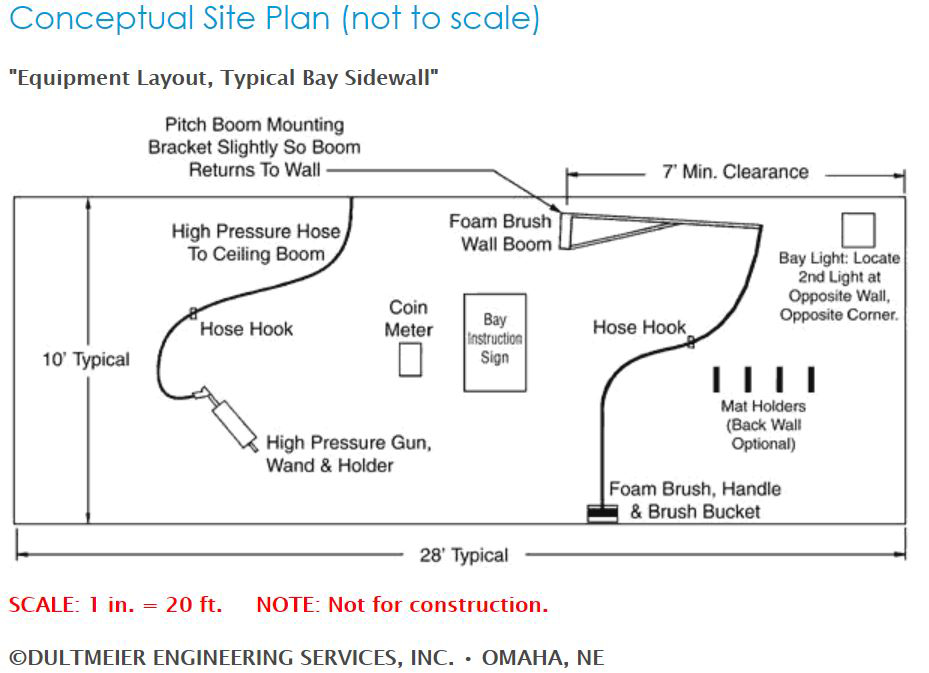
    Car Wash Equipment Layout Site Plan


    Additional Revenue Streams

    Do not overlook vending products such as towels, Armorall, window cleaner and fragrance trees. These are additional revenue streams. Piggybacking off vending machines, every wash should have bill changers. This is an absolute necessity. Studies have shown a minimum 10% increase in gross revenues for washes that have bill changers.


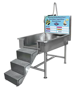
    Pet Washing Station


    Another trending area that has taken off in the past few years is the addition of pet washes at car wash facilities. The demand is there and many people will wash their cars and pets in the same visit. This has been a profitable investment for our customers who have installed pet wash facilities at their locations. You can view some options here. As always, should you have more questions than can be answered by our website don't hesitate to contact us.

    (0) Chemical Compatibility - Hose, Pumps and Fittings

    Have you ever encountered a nightmare situation where a hose miraculously turns into an icky, nasty, pasty goop? Or how about a pump that starts leaking from virtually every connection point and fitting? What about a fitting that has a pinhole worn through it after only a few days in service? These are all scenarios we have witnessed and can help prevent. Here's how we are going to get you set up with correctly identifying chemical-compatible products and solutions from the get-go.

    Importance of Ensuring the Chemical Compatibility Between Solutions and Product Material Used

    It is extremely important when working with any variety of chemicals or solutions that pumps, hoses, fittings and safety items are correctly matched for chemical compatibility. Most manufacturers offer chemical resistance charts for their specific product lines and are readily accessible when required. Check out a thorough chemical compatibility chart from Dura Products in our Resources Library. And if that chart isn't enough here is another resource for you. For the safety of you and your employees, it is critical that a proper analysis is made between the solutions you will be handling and the products used to transfer those solutions.


    Grant Me Free Access to Parts Library


    Product Warranty Issues

    Also, most manufacturers will not warranty products for compatibility issues if an analysis was not properly completed - prior to product use. If it is concluded that a specific chemical compatibility issue caused a product to fail or perform there will be, in most scenarios, no warranty granted by the manufacturer. Failure to perform a proper chemical compatibility check prior to solution handling could result in catastrophic failure of your equipment and extensive unnecessary costs due to downtime and repair/replacement of equipment and components.


    chemical compatibility issues


    Common Incompatibility Issues between Product Material and Solutions based on our Experience 

    We have seen EPDM hoses turn to mush when used to transfer oil-based products. Similarly, we have witnessed pump elastomers (seals, O-rings, gaskets) completely deteriorate and create an environment where metal is creating friction against metal inside of pumps. Without elastomers inside a pump, it cannot function properly. Furthermore, we have seen PVC fittings completely deteriorate after only one to two weeks in service.

    All of these scenarios could have been avoided had the operators approached us beforehand and identified the solutions to be transferred with their initial choices of products. Should you ever have questions about chemical compatibility - don't hesitate to contact us - that's what we are here for.

    Common construction materials for pump bodies and housings are Polypropylene, Stainless Steel, Cast Iron, Kynar (PDFV), Brass, Bronze and Aluminum. Materials generally used in constructing pump seals are Viton, EPDM, Buna, Hytrel, Teflon and Santoprene. Common construction materials for fittings and accessories, such as strainers and valves, include Polypropylene, Nylon, Brass, Stainless, Cast Iron and Acetal.

    Hoses and tubing are generally constructed of Buna, EPDM, Viton, Teflon, PVC, EVA, Polyethylene or Neoprene. That being said, your specific application could call for a unique material to be used - given the parameters of the solution you are transferring.


    Next Steps - Identifying Suitable Product based on Solution

    Once we have identified the solution we are transferring we can then determine what products are suitable for the transfer of that solution. Here at Dultmeier Sales we don't guess - we want to do as much as possible to ensure chemical compatibility from the start. If there are ever questions as to what a solution consists of - you should acquire an SDS or Safety Data Sheet. This document was formally known as an MSDS (Material Safety Data Sheet).

    By acquiring an SDS we are able to see the highest concentration of a substance in a percentage breakdown. It is always best practice to find a product that can safely handle all substances that make up a solution. That being said, that is not possible in every scenario. In those instances, one should identify the top substance(s) and locate a product that is chemically compatible. Safety items such as gloves, aprons, boot covers, and arm covers are commonly offered in Neoprene, Nitrile, Latex, PVC.


    Request FREE Catalog


    The first step for proper handling and transfer is to check both the body and the seals of your pumps for compatibility against any number of chemicals. Remember to consult the SDS of the product(s) you are handling. The pump body may be rated to handle a specific chemical but the seals may not. Also, valves and diaphragms need to be reviewed as does any material that will come in contact with a specific chemical or solution.


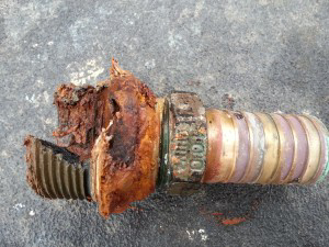
    fitting failure due to chemical compatibility


    If we don't perform this step our operation will most assuredly come to an inevitable halt - due to failure to properly identify chemical compatibility. Another note to be aware of is that if you choose to mix multiple chemicals and transfer with one pump - we cannot definitively say what chemical reactions will take place with your elastomers, hoses, fittings, etc.

    When you mix multiple chemicals together you have just altered the chemical makeup of the solution. We recommend avoiding this scenario unless you are certain the products you are mixing are like products.

    If the pump construction is compatible, next check against fittings and hose that will be used in the application. We cannot stress this enough - always check compatibility with any and all items that will come in contact with the chemical or solution. As a general rule Kynar and Teflon are used for very aggressive solutions but are at the high end of the cost spectrum.

    There are some more economical options in EPDM, Viton, and Buna. EPDM and Viton may work fine for soaps, waxes, and some herbicides and/or pesticides. Do note that Buna is not suitable for many agricultural chemicals, but is compatible with petroleum-based solutions. While EPDM is compatible with many chemicals, it is not suitable for oil-based products - stick with Viton or Buna in those scenarios.

    Key Parameters to Consider: Temperature & Pressure

    Furthermore, it is important to confirm temperature and pressure as these two variables can also affect compatibility. Temperature and pressure should always be taken into consideration as they can vary with every application or between applications. For instance, a chemical may respond differently to changes or fluctuations in either temperature and/or pressure.

    The fluctuations may actually cause the chemical to completely alter its structure and no longer be compatible with elastomers or products that were previously identified as chemically compatible. Long story short, you may be fine transferring and handling a product at ambient temperatures but may find an issue at higher temperatures or pressures.

    Remember to check for compatibility with all of the item groups above. Any chemicals or solutions that you may be handling or transferring should always be confirmed with an SDS - if chemical compatibility is in question. Think chemical compatibility first for the safety and protection of yourself and others. Furthermore, we want to ensure greater longevity and performance of your pumps, valves, fittings, and hoses. Request a Free Catalog here.

    If you enjoyed this post check out our technical library for more resources. Can't find what you're looking for? Give us a buzz or drop by our website. Be safe out there.

    (0) Water Hardness and Total Dissolved Solids

    Low water hardness and low TDS (Total Dissolved Solids) are critical for proper cleaning and reduction of water spotting in car and truck wash applications. Water hardness is measured in grains of hardness. Typical drinking water can range from 100-250 grains of hardness. However, water hardness under 5 grains is usually best for the most efficient use of detergents or soaps in vehicle cleaning.

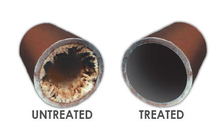
    A water softener is usually required to get hardness down to zero grains which is necessary to, in turn, get TDS down to zero. The size of the softener required is a function of the quality of the incoming water, as well as, the gallons required in a typical day for a specific facility. Left untreated, high mineral content in a plumbing system can tremendously affect the efficiency of the plumbing system, as well as, reduce the life of pumps, valves, and other equipment.


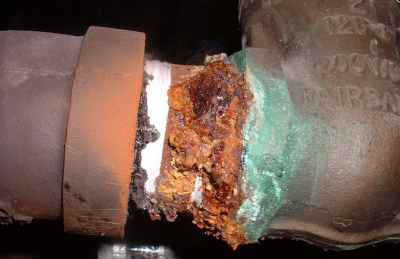
    Treated vs Untreated Water Pipes


    TDS (Total Dissolved Solids) is the makeup of minerals, salts, metals, etc. that are present in a volume of water. This can include any inorganic element that is present in water other than pure (H20) water molecules. Typically TDS is measured in PPM, (Parts per million). The EPA allows up to 500 PPM for human consumption in water but vehicle washes need to be in the range of 0-50 PPM to rinse and dry without spotting.

    Therefore; typical reverse osmosis, spot free rinse vehicle system will produce zero parts per million (PPM) of TDS when the filter/membranes in the system are new. Thin-film Composite or Cellulose Acetate membranes are designed to reduce zero grain water to zero TDS water. As membranes provide the filtering process over time, they will begin to plug or foul. The amount of time for this to occur depends on water usage and flow.


    New Call-to-action


    Typical testing will show TDS increasing, with spotting occurring about 40PPM. At this point, membranes should be replaced which will bring the TDS back to zero and the process begins again. Membrane material differs and is specifically designed for tap water, brackish water and seawater. Tap water membranes are used with typical city supplied water.

    There are many simple devices available to test for water hardness and TDS to ensure your softeners, spot-free rinse system and filters are operating properly and efficiently. If you have further questions about reducing the amount of total dissolved solids in your business plumbing system give us a call at 1-888-677-5054 or visit us here. Take care!