


We all know the key role fertilizer plays in crop production. Handling large volumes of these vital plant nutrients requires the right transfer equipment. At the heart of every fertilizer transportation system is the pump. Whether it is unloading rail cars or filling the tanks on your planter, the type of pump you use has an impact on your ability to run your operation smoothly.
In this guide, we'll dive into the various types of fertilizer pumps. We will also look at the specific characteristics and attributes that hold up to the rigorous nature of transferring fertilizer.
Understanding Fertilizer Transfer Pumps
The primary pump type used for high-volume transfer of fertilizers is a centrifugal pump. Known for their simplicity and effectiveness, They are ideal for any scenario where the goal is to transfer fluid as quickly as possible. In other words, high-volume transfer scenarios such as loading or unloading semi-tankers, emptying rail cars, loading sprayers, applying liquid on fields, etc.
Now, centrifugal pumps are not the only pump types used to handle fertilizer. There are many different positive displacement pumps used to apply fertilizers on planters or toolbars, and there are gear pumps used for some more viscous products, but centrifugal pumps are the primary choice for high-volume transfer.
Advantages of Centrifugal Pumps for Fertilizer:
- Simple
- High-flow
- Easy to repair
- Durable
Disadvantages of Centrifugal Pumps for Fertilizer:
- Low pressure relative to other pump types
- May not handle really heavy or viscous products
- Cannot be run dry unless they have a lubricated seal
How Fertilizer Transfer Pumps Work
Before we get to the dirty details of fertilizer pump selection, it is worth your time to get familiar with the basics of centrifugal pumps. Especially, if you aren't familiar with them or need a quick refresher. If you want to jump straight to the pump selection, click here to jump ahead.
In order to gain a thorough understanding of how a centrifugal pump works, we should first look at the main components. These are the housing, the impeller, the shaft, and the shaft seal. Depending on the specific type of pump and the design there may be other components like a pedestal, volute, bearings, etc., but these are the main pieces that make up all centrifugal pumps.
Basic Components of a Centrifugal Fertilizer Pump:
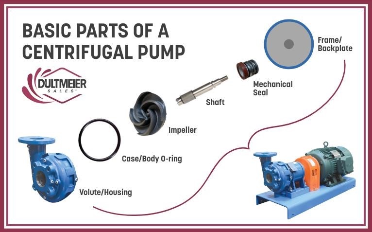
- Housing
- Volute
- Impeller
- Shaft
- Seal
- Gasket
- Pedestal/Adapter
A centrifugal pump operates by using centrifugal force to move liquid. The impeller, mounted on the shaft, is driven by a motor or engine. As the shaft rotates, the impeller also rotates. The rotation of the impeller creates centrifugal force, which pushes the liquid inside the pump away from the center (the eye of the impeller) towards the outer edges
Pump Curves
Variations in pump construction result in different capabilities, such as flow rate, head, horsepower, and efficiency points. These differences arise from the various pump sizes, the shapes of the pump volute, as well as the sizes and designs of impellers. These factors alter the pump curve, which represents the pump's performance based on discharge plumbing parameters.
All these different variations mean that it is important to look at a pump curve when choosing a pump and not just physical attributes such as the port size or horsepower. Those alone don't tell the whole story.
A pump curve is a graphical representation that shows the relationship between the flow rate and the head (pressure) of a pump. It illustrates how a pump performs under different conditions, helping users determine the best operating point for efficiency and effectiveness. By understanding the pump curve, you can select the right pump and the horsepower needed for your specific application, ensuring optimal performance and energy savings.
How to read pump curves
For more detailed information on centrifugal pump operation and pump curves, be sure to read this detailed guide on centrifugal pumps written by Tom Hansen, Head Engineer at Dultmeier Sales.
Selecting a Fertilizer Pump
Now that we have a solid understanding of how a centrifugal pump operates, Let's look at the different aspects you should consider when choosing the right one for your needs.
Straight Versus Self-Priming
While there are many variations and different designs, all centrifugal pumps fit into two main categories: straight and self-priming. Both of these types operate on the same basic principle, using centrifugal force to move liquid. They differ in their ability to maintain liquid inside the pump. This is an important factor to consider when you select a pump so let's examine this a bit further.
Self-priming pump
A self-priming centrifugal pump can pull liquid from a level that is below the pump inlet (assuming it is properly primed initially). This is achieved via a combination of the design of the volute and suction created by the pump. A self-priming pump is designed to store fluid in the housing even after it stops running. Thus keeping the pump seal protected when it is started again and it begins to prime.
Priming is important because a standard centrifugal pump requires liquid in it at all times to lubricate the shaft seal. I say standard because there are centrifugal pumps that can be run dry but more on that later.
This video thoroughly explains the principles of pump priming:
Self-priming pumps are often used as transfer pumps to load and unload sprayers or nurse tanks. They provide more flexibility in this scenario because they do not have to be installed lower than the tank outlet. This means they can be installed almost anywhere on a truck or trailer and pull liquid from the tank.
Straight centrifugal pump
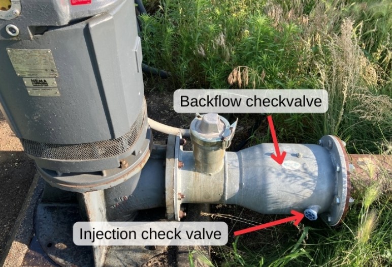
A straight centrifugal pump will also create suction the same way that a self-priming pump does, however, due to the design of the pump volute, they do not store liquid. The inlet of the pump must be gravity-fed so that the pump is not operated without liquid. If the pump inlet is not gravity-fed (flooded suction), You can use a check valve or foot valve in the suction line to trap fluid in the pump. This will protect the seal from cavitation when it starts again.
These pumps are generally more efficient than self-priming pumps. They are simpler machines, with impellers and casings designed for hydraulic efficiency. Self-priming pumps, on the other hand, have additional features like a priming chamber that can create turbulence and energy loss, making them less efficient.
A straight centrifugal pump uses most of its energy for pumping, whereas self-priming pumps must expend some energy on the priming process, reducing their overall efficiency.
Straight centrifugal pumps are very common in scenarios where the pump is going to be permanently installed with a flooded suction port:
- Bulk transfer from large storage tanks
- rail unloading, etc.
- onboard sprayers
- planters
- fertilizer toolbars
Choosing between a straight centrifugal pump and a self-priming centrifugal pump depends largely on your specific application needs. Self-priming pumps are versatile and work for many applications, but if you want efficiency and the pump will have flooded suction, then a straight centrifugal pump is generally the best way to go.
Types of Fertilizer Pump Drives
Another aspect to consider when selecting a centrifugal fertilizer pump is the means you will use to drive it. A pump can be driven any way you want as long as you have enough horsepower to handle the application.
Common centrifugal pump drive types used for fertilizer transfer:
- Electric Motor
- Hydraulic Motor
- PTO Driven
- Gas-Engine
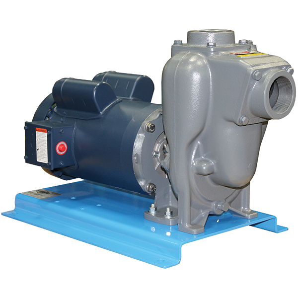
Electric Motor Units
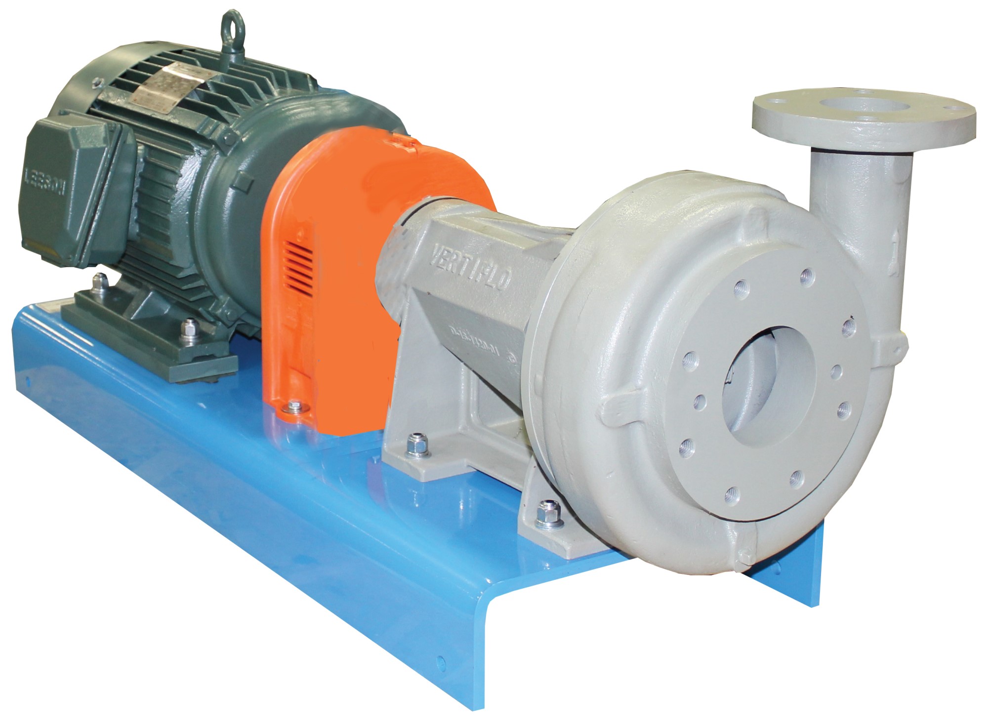
Electric motor-driven units are the most common drive type in fertilizer facilities. There are two different pump and motor unit styles: close-coupled and long-coupled. As the name suggests, a close-coupled is where the pump is directly bolted to the electric motor. Long-coupled pump units are connected with a set of couplers.
Close Coupled Pump & Motor Units
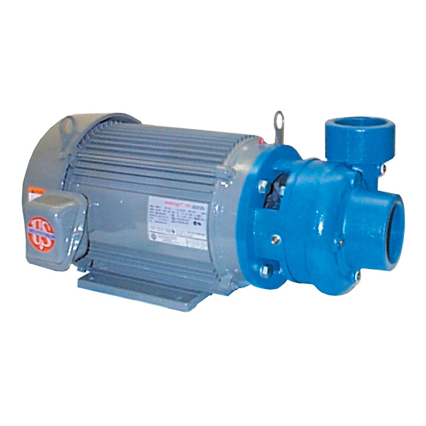
A close-coupled pump unit is a much simpler design that has many benefits. Both self-priming and straight centrifugal pumps can be coupled with a C-face motor. Pump manufacturers build pumps with motor adapters to mate with several different electric motor frame sizes.
Pros:
- Compact design
- less expensive
- easy to connect
- No alignment issues
Cons:
- Leaking around the pump seal can damage the motor
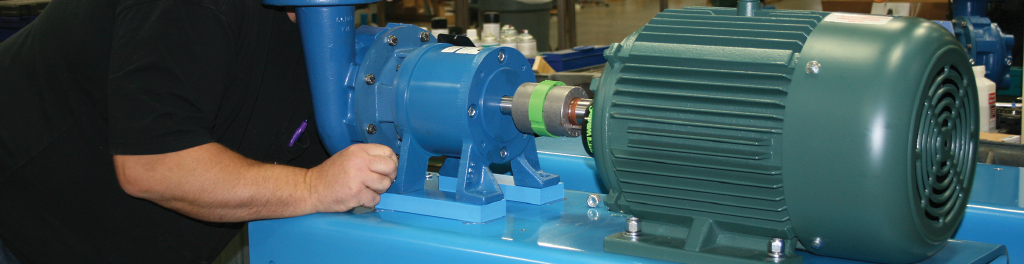
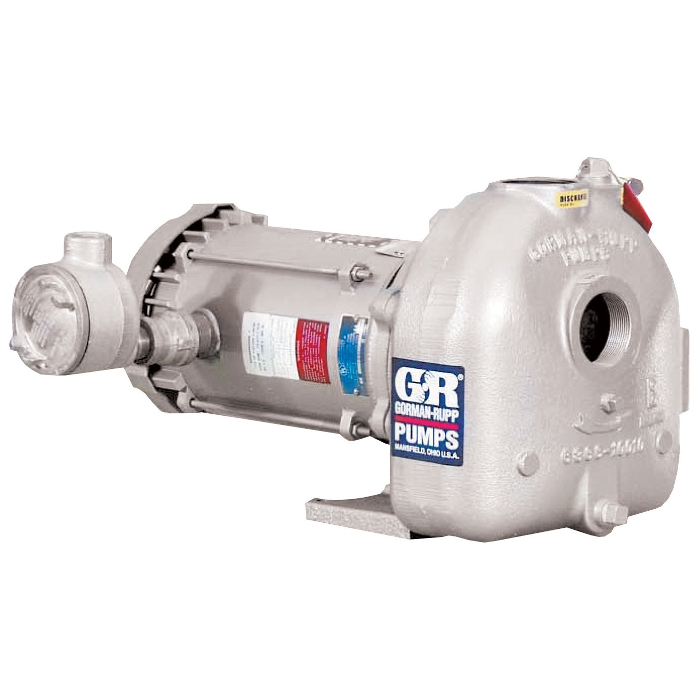
Long Coupled Units
Although they are more complex and expensive, long-coupled units have many benefits. They typically consist of a baseplate, a 3-piece flexible coupling, and the pump and motor. Pumps used for long coupled units are called pedestal pumps. This indicates that they have a bearing pedestal with a solid shaft.
Pros:
- Design protects motor bearings from leaks
- Flexibility for more pump and motor combinations
Cons:
- Requires precise alignment
- Can be more expensive due to the baseplates and couplers required
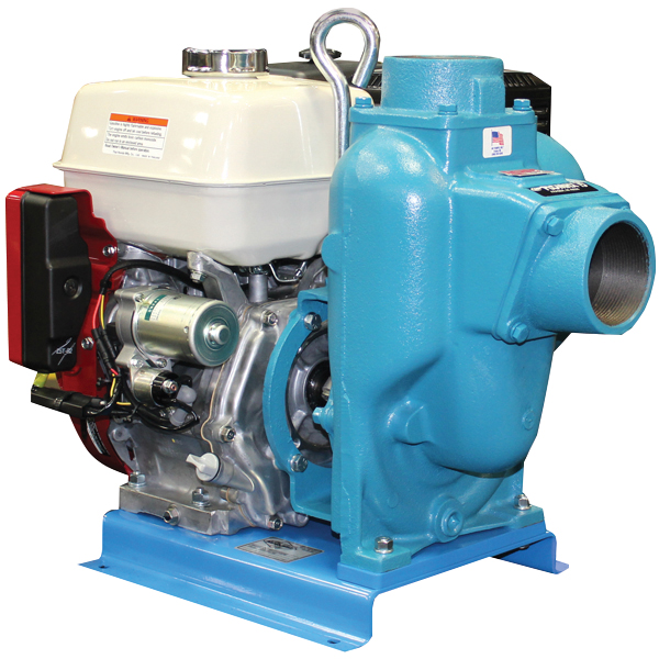
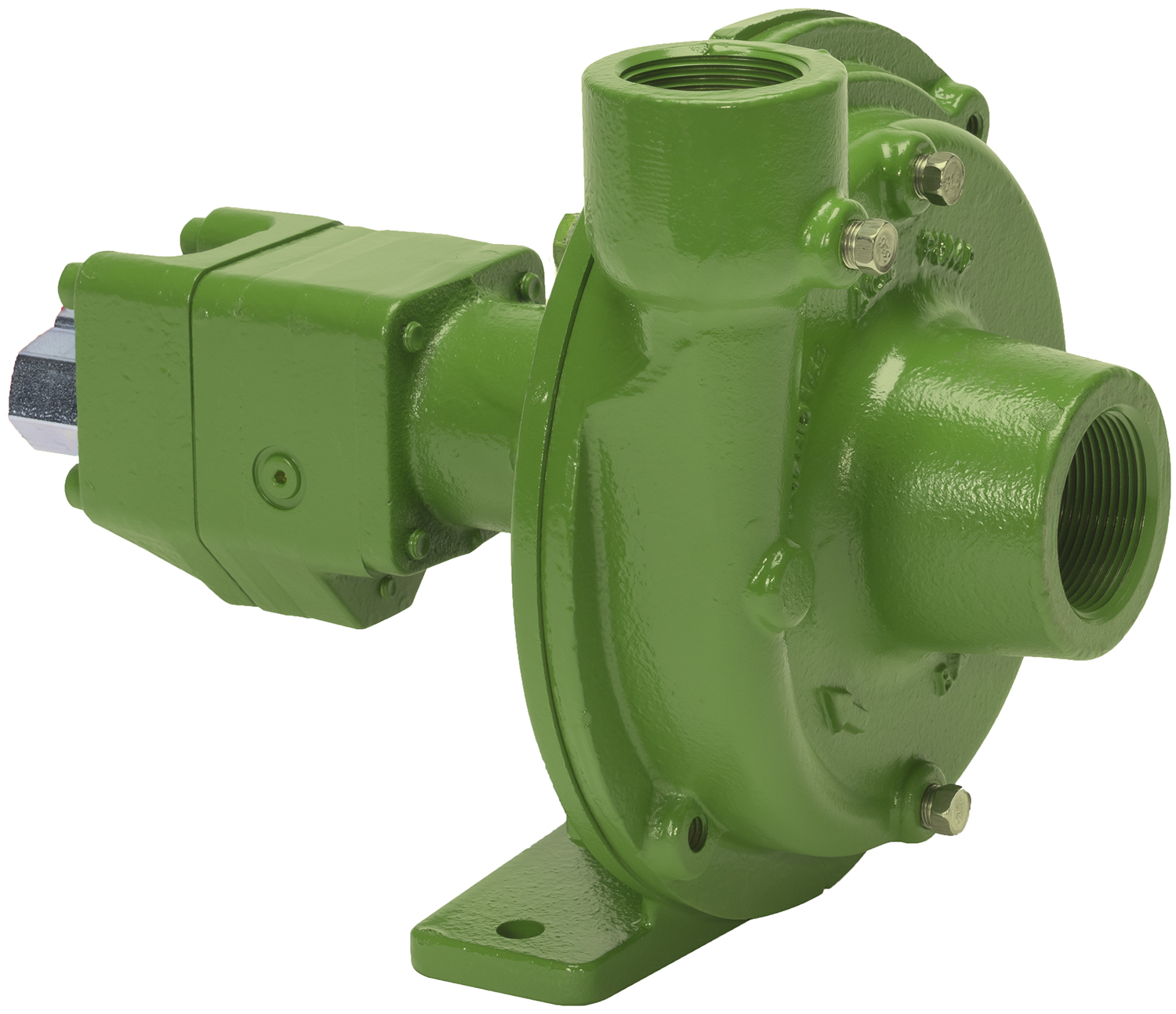
Engine-Driven Pumps
Pumping fertilizer on a nurse/tender trailer or a tanker limits the power sources, so typically we will use engine-driven pumps. For fertilizer, Banjo, MP, John Blue, and Scot offer engine-driven pump units fitted for fertilizer. The horsepower requirements are higher to move fertilizers that are heavier than water. For 2-inch pumps this general means an 8hp engine, and 3-inch pumps will need 13hp.
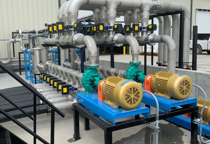
Like electric motor pump units, there are a variety of variations available. From manifold flange pumps, poly, cast-iron, and stainless steel:
Engine Driven Pump Units:
![]()
John Blue 3-Inch Fertilizer Pump
View Other Engine-Driven Fertilizer Pump Options
Consider Chemical Compatibility
Compatibility is a crucial factor to consider. As you know, fertilizer is a broad term encompassing several different liquids used to improve plant growth. Most of these products possess properties that lead to rust, corrosion, and friction wear on pump components.
Centrifugal pumps can be constructed using various types of materials. Due to the wide variety of chemical properties of the different fertilizers, there isn't one material that works best for all of them. It is important to look at individual products to determine the best material to use.
Common Fertilizer Pump Materials
Although no material will handle all types of fertilizers, there are some that work with common fertilizers such as 10-34-0 or 32% nitrogen. For these products, we recommend polypropylene or cast iron pumps with Viton mechanical seals. Stainless steel is another material that will work with a broad range of fertilizers, but due to the cost, it is only used when necessary.
If you are not sure what materials are best suited for the type of fertilizer you use, you can refer to our chemical compatibility charts or call us for help. Our years of combined experience give us a good idea of what materials should be used with different products.
Regardless of pump type, it is recommended to drain corrosive liquid from the pump and fill it with a non-corrosive liquid such as crop oil or RV antifreeze. This will significantly prolong the life of cast iron pumps.
Choosing A Seal Type
No matter what type of centrifugal pump you are using, the shaft seal is the most important component to understand. The seal provides a barrier keeping liquid in the pump as the shaft rotates.
There are different types of seals used in centrifugal pumps, but the most common we see used with fertilizer is a mechanical seal. This type consists of two seal faces, an elastomer, and a spring:
- Rotating Seal Face: Attached to the pump shaft and rotates with it.
- Stationary Seal Face: Fixed to the pump housing and remains stationary.
- Elastomer: keeps the rotating pieces tight on the shaft.
- Spring: Pushes the two faces together to maintain a tight seal
Each seal face is smooth and consists of durable materials such as silicon carbide, carbon, or ceramic. The seal elastomers can be Buna, EPDM, Viton, or other material that is compatible with the fluid you are pumping. While the pump is operating a small amount of the fluid being pumped forms a barrier between these two seal faces. This lubricates the seal and provides a barrier that keeps the pump from leaking around the shaft.
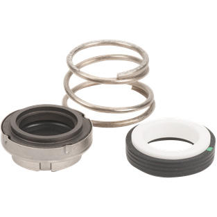
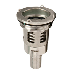
Viton® mechanical seal assembly
Without liquid in the pump housing, a standard mechanical seal can fail because it is not lubricated. This is called "running a pump dry". The two faces rub together creating friction that will harm the seal face or crack it all together. Even slight damage to the seal face can result in a leak.
Using a pump with a lubricated seal or double seal assembly can prolong seal life. These mechanisms keep the shaft seal of the pump lubricated with antifreeze or grease. This adds protection in situations where the pump might run dry, like unloading trucks or storage tanks. Any situation where a tank is emptied or prime could be lost.
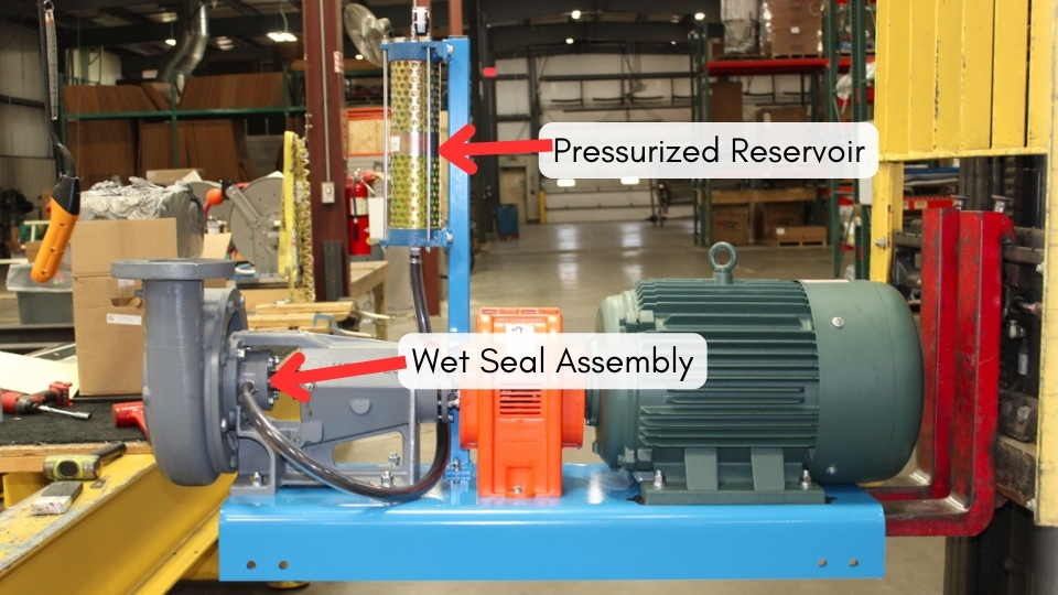
Pressurized wet seal assembly on fertilizer pump & motor unit.
If your pump will be installed in a scenario where it could be running dry or you don't want to risk seal failure in the middle of your busiest season, a double seal or lubricated seal is your best option.
Pump Size
When we say pump size, we are talking about flow rate. The amount of liquid you need your pump to move in a given amount of time is important, but determining what pump will deliver your needed flow rate can be tricky.
The flow rate in centrifugal pumps is closely tied to the discharge head. An increase in discharge head leads to a decrease in flow rate, and vice versa. Understanding this relationship is essential for selecting and operating these pumps, as it directly affects their performance in various scenarios.
Of course, no two scenarios are the same so let's explore how you can go about sizing a fertilizer pump for a specific application.
Sizing A Fertilizer Transfer Pump
First, you need to consider the specific fertilizer you are going to be moving as well as the plumbing layout. This process involves gathering some information, here are the basic steps:
- Determine Desired Flow Rate: Calculate the required flow rate in gallons per minute (GPM). Consider the application, are you filling tanks? Unloading trailers? How quickly do you want the load/unload process to be completed?
- Identify Your Fertilizer Properties: Determine the viscosity and density of the fertilizer.
- Calculate Total Head (TDH): Determining the total discharge head of a pump involves calculating the total head or pressure that the pump needs to overcome to move the fluid through the entire system. If you have plumbing in place already, consider any restrictions such as elbows, valves, strainers, meters, vertical pipes, etc. For more details, you can read this guide that further explains total dynamic head.
- Identify Pump: Once you know your flow rate and TDH, you can identify a pump that can achieve your desired GPM given your plumbing setup. This requires examining the pump curves of different models to find a suitable option. The pump curve will offer insights into the most efficient option and the required horsepower for your application.
The total dynamic head, the pump design, and the flow rate, combined with the viscosity and weight of the fertilizer will determine how much horsepower is required. Determining pump flow rates and horsepower requirements is a complex matter. If you have questions or just want us to walk through this process, you can give us a call any day and we can help you determine the pump and motor size you need.
Final Takeaways
Choosing the right fertilizer pump is crucial for efficient and smooth operations. By understanding the advantages and disadvantages of different pumps and the specific needs of your application, you can make an informed decision.
Remember to consider factors such as pump type, drive methods, material compatibility, seal types, and proper sizing to ensure optimal performance and longevity of your equipment. Investing time in selecting the appropriate pump will ultimately lead to better handling of fertilizers, increased productivity, and cost savings in the long run.
There are many, many different options for fertilizer pumps, so do not hesitate to reach out to us if you need some guidance selecting a pump!

Tech Ag & Industrial Sales
Shane Blomendahl is a tech sales veteran at Dultmeier Sales with over 10+ years of experience in liquid handling products covering several industries and applications.


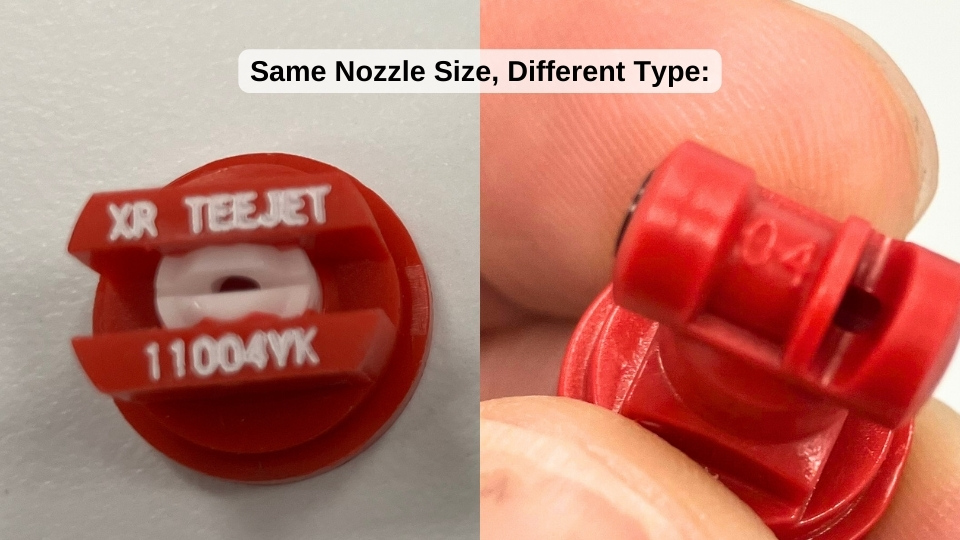
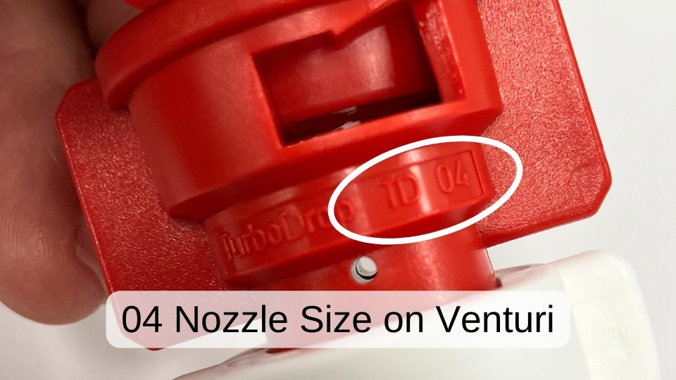
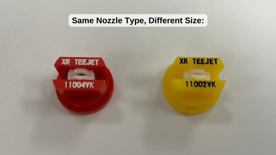 The red nozzle is an 04 size and the yellow nozzle is an 02 nozzle.