


Pressure tanks are used in a variety of applications, but a common usage is system efficiency. For example, one reason someone might install a pressure tank in a plumbing system would be to keep the pump from constantly running. In doing so, the pressure-regulating tank increases the longevity of the pump/motor and reduces maintenance and down time - ultimately resulting in lower operating costs. Let's dive into a step-by-step how to of sizing a pressure tank.
Contents
0.1 Info You NEED to KNOW Before Starting
0.2 General Rule of Thumb for Sizing a Pressure Tank
Info You NEED to KNOW Before Starting
Before beginning the process of sizing a tank, there are a few important important input data points to know in order to properly size a pressure tank:
- Flow Rate
- Cut-in/Cut-out Pressure
- Target Run Time
A general rule of thumb, that most manufacturers suggest, is a run time of less than one minute if the horsepower is less than 1HP. If the motor is over 1HP, then a good guideline to follow, is a run-time of 2 minutes or more. Always confirm this, with your tank manufacturer of choice, as guidelines can vary.
General Rule of Thumb for Sizing a Pressure Tank
Generally, as a rule of thumb, one can follow these guidelines when sizing a pressure tank:
- 0-10 GPM: 1 gallon of drawdown per 1 GPM of flow
- 10-20 GPM: 1.5 gallons of drawdown per 1 GPM of flow
- 20 GPM+: 2 gallons of drawdown per 1 GPM of flow
Drawdown can be defined as the amount of volume loss in the tank as the plumbing system "draws" off this pent up pressure. After all, the purpose of a pressure tank is to maintain pressure in a given system and give the pump a break. This way, the pump doesn't need to run constantly to remain at system pressure. While a pressure tank can appear costly up front, it will save in the long run. Less run time for the pump means less maintenance and less money in energy costs.
There are various orientations of pressure tanks and the most common are horizontal, inline, and vertical. Be sure to determine which orientation works best for your plumbing setup.
Once we have identified our flow rate in gallons per minute (GPM), have identified our cut-in/cut-out pressure, and confirmed our target run time - we must determine what cut-in/cut-out pressure we want to set the system at.
Pressure Tank Sizing Explained
An important equation to remember when sizing a pressure tank is below:
Flow Rate X Run Time = Tank Draw Down Capacity
Example:
Let's say we have a pump that produces 5 GPM and is ran by a ¾ HP motor. Since I'm operating a motor that is less than 1 HP, we are going to assume that "ABC Manufacturer" recommends a 1-minute runtime. We want to design this system to cut-in (turn on) at 40psi and cut-out (turn off) at 60psi.
5 (Flowrate) X 1 (Runtime) = 5 gallons of Draw Down (at 40/60PSI)
So, I will need to select a tank that allows for 5 gallons of draw down at a pressure setting of 40PSI cut-in and 60PSI cut-out. If I need a vertical tank, I could select a WOMAX-220. If my plumbing layout would accommodate a horizontal tank better, I could select a WOMAXH-220. This would give me approximately 3.5 minutes of run time before the pump would cycle back on. Horizontal pressure tanks have a plastic pump stand so you can maximize space when designing a plumbing system. This is certainly a nice feature when working in confined spaces where space is at a premium.
Relationship Between Pressure & Tank Size
An important thing to remember, the higher the operating pressure - the larger the tank must be. Pressure and tank size have a direct correlation - as one increases, so does the other. The higher the pressure setting, the less the drawdown is and thus, the need for larger tank capacity.
![]()
After we have these three points determined, we can then proceed with sizing a pressure tank. Pressure settings are another important factor with any plumbing system. The most common pressure settings are 30/50; 40/60; 50/70. Most manufacturers will have a pressure tank sizing chart that will allow viewers to quickly size a tank's drawdown based upon their system's pressure settings.
We can supply you with this information on the Wilo MaxAir® product line if you want to get into the details. Just give us a ring or visit www.dultmeier.com 24/7. Here is a drawing of a Wilo MaxAir® horizontal tank that outlines some features which set this product line apart from the rest of the pack and really make it one of the top line products in the marketplace.
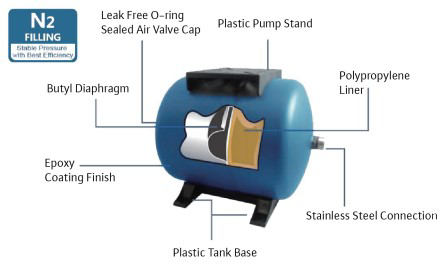
Cutaway of Wilo MaxAir Horizontal Pressure Tank
You can view the full offering of Wilo MaxAir® Pressure Tanks Right Here on dultmeier.com. As always, should you have further questions about pressure tank sizing or other applications - don't hesitate to contact us. That's what we are here for. Your Experts in Delivering Fluid Handling Solutions - We Know Flow!