Search
Call for Live Order Assistance & Technical Support (7:30am-5pm CST)
Menu Close
RSS

Blog

(0) All You Need to Know for Goodall Anhydrous Ammonia Hose

The fall/spring application of the fertilizer Anhydrous Ammonia, also known as NH3, is always a hectic time for those in the agricultural industry. The race to get the precious fertilizer in the ground is fast-paced and everyone is running like gangbusters. Every season fall/spring we field phone calls that stem from concern due to the reliability and service of ammonia hoses.

This post should clear up many questions and will provide some valuable education to you and your team. Below you will find a listing of common questions we run across throughout a season. As always, we are happy to help share our wealth of technical knowledge and experience.

Common Anhydrous (NH3) Hose Questions

Residue on NH3 Hose Exteriors

Question: At times a residue forms rings or cones all over the cover of my anhydrous ammonia hose. This residue resembles or looks like white spots.

What causes this residue to appear and what is it?

Answer: Anhydrous ammonia hoses are designed to allow a small amount of gas through the wall of the hose. This is known as pinpricking and it is a safety requirement. This allows trace amounts of NH3, to permeate through the tube. The pinpricks allow minute amounts of anhydrous ammonia to easily escape into the atmosphere through the hose cover. There is such a trace amount of anhydrous ammonia being released that it is not harmful.

A hose that has been improperly pricked will cause the cover to blister and eventually blow out - this is the same for a hose that has not been pricked at all. A hose blows out when NH3 becomes trapped between the layers in the hose, heats up, and vaporizes - thus causing rapid expansion and bursting through the hose cover.

The single drawback to pin pricking is the residue that is left on the hose and the resulting appearance that the hose is somehow defective, after use. Remember, as the anhydrous ammonia escapes through the pinpricks it comes in contact with the atmosphere and forms the white residue that many operators commonly see throughout the season. The color and consistency of the residue are affected by the amount of dust and relative humidity present in the atmosphere.

This residue does not indicate a defective hose and in no way should be viewed as a problem or unsafe situation for operators. Furthermore, it is a reminder of this built-in safety feature of the anhydrous ammonia hose and that it is, in fact, working as intended.


Blog Heading


NH3 Hose Basketing

Question: My stainless steel braided anhydrous ammonia hose has ballooned out behind the coupling.

Why is this happening?

Answer: The symptom described above is referred to as "basketing". Basketing is the result of the thermal expansion of trapped anhydrous ammonia in the hose. By design, the hose is intended to expand in a controlled fashion when this over-pressurization occurs. Most commonly, a user will see basketing form behind the coupling - this intended consequence is meant to keep the NH3 hose from a catastrophic blowout.

Thermal expansion generally occurs when anhydrous ammonia remains or leaks out of a shut-in hose assembly and is allowed to heat up or "cook" in the sun. Extremely high pressures occur, internally, as the black hose is exposed to sunlight for extended periods.

It is highly recommended that all hose assemblies be emptied before storage and downstream valves are checked for compliance and acceptable operation regularly. Furthermore, hydrostatic relief valves should also be checked for correct operation and compliance pressures depending on state and local fire marshal requirements.

Anhydrous Ammonia Expected Service Life

Question: What is the expected service life of an anhydrous ammonia hose? 

Answer: Factory-assembled NH3 hose assemblies come in three variations that each have a different service life. Each type is labeled with a removal date. Here is the life span for the different ammonia hose assemblies that we carry at Dultmeier:

Goodall New Hose Expected Service Life - When Coupled by Authorized Goodall Locations:

N1446 - Super Long Life - 10 Year

N2595 - Rifleman - 8 Year

Park New Hose Assemblies Expected Service Life - When Coupled by Authorized Parker Locations:

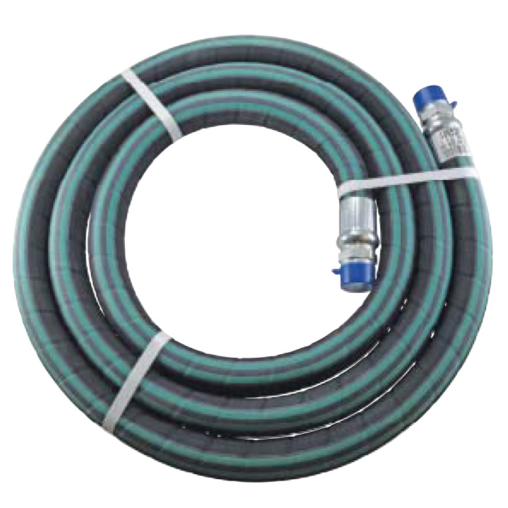
7262 Green Stripe - 6 Year 

AN05015 NH3 - Anhydrous Ammonia Hose

Maintenance and Care of Anhydrous Ammonia Hose

Recommended Anhydrous Ammonia hose maintenance and care instructions:

New Hose

  1. Ensure you have the correct hose. All Anhydrous Ammonia (NH3) hose will be strip branded, stating that the hose is for Anhydrous Ammonia, the working pressure, the name of the manufacturer, and the month and year the hose was made.
  2. Make sure the couplings are properly put on. After the hose is charged with anhydrous ammonia, check that the couplings are secure and that they have not moved.
  3. Ensure that the new hose is free from cuts, gouges, and imperfections. Perform a visual check of each hose in service. Run your hand down the length of the anhydrous ammonia hose, checking for soft spots.
  4. Never secure the coupling in a vise when attaching valves.
  5. Goodall highly recommends that all relief valves be replaced at the same time a new hose is installed.
  6. If any of the above imperfections are found to be existent, remove the hose from service immediately.

Used Hose

An anhydrous ammonia hose that is currently in service or has been carried over from the previous year:

  1. Applicators should remove anhydrous ammonia hoses from the nurse tank(s) before winter and store in a cool, dry place. Keep away from direct heat and any motors that are operating. The best place to store an anhydrous ammonia hose is to hang the hose in a vertical position from the shoulder of the coupling. By doing this one relieves stress on the hose. The hose will be out of the way so as not to be damaged by individuals walking on it, trucks driving over it, or anything being piled on top of it. Furthermore, the storage of anhydrous ammonia hoses indoors prevents damaging UV rays from the sun ruining the hose.
  2. NH3 hoses should be checked in the spring in the same manner as a new hose is inspected - this way the user ensures that an Anhydrous Ammonia hose is, in fact, an Anhydrous Ammonia hose.
  3. Each hose should be checked at least daily, if not each time the hose is used, to ensure proper function. Make sure to check for movement of couplings, cuts, gouges, or cracks in the cover. Check for any soft spots - this is done by running your hand down the entire length of the hose.
  4. Should any of the above imperfections in an anhydrous ammonia hose be found, immediately remove the hose from service.

Always remember - visual and manual inspections SHOULD BE DONE DAILY.

Don't hesitate to contact us should you have any questions. Be safe out there...

(0) Farm Fuel Transfer - How to Decrease Filling Times

A common misconception with any pump, for that matter, is that the flow rating of the pump is the output that a user will see - regardless of the plumbing system that the pump is installed into. For further explanation check out one of our previous blog posts about centrifugal pump sizing, applications and how a plumbing system affects pumps differently.

While most 12 Volt fuel pumps are not centrifugal pumps the flow rates of these pumps is still drastically affected by the plumbing systems in which they are introduced into. Think of it this way - while your car speedometer maxes out at 160 mph you certainly can't drive the vehicle that fast - at least for an extended period of time without catastrophic failure. A pump is very much the same - while it may be rated to 25 gallons per minute (GPM) that doesn't mean that you will see flow rates equivalent to that output.

One solution to decrease filling times is to evaluate your plumbing system. Do you have 3/4IN lines? Can you bump up to 1IN? Remember, the greatest thing we can do in order to increase the efficiency of our plumbing system is to increase the size of the plumbing system. How about a high flow fuel nozzle?

If we simply have a standard flow nozzle that will certainly affect your flow rates in a negative manner. Keep in mind that many 12 Volt transfer fuel pumps from manufacturers such as Fill-Rite or GPI are rated 20-25 gpm. Now if you have nozzle at the end of your plumbing system that is rated only to 20 gpm don't think that your 25 gpm pump is going to achieve that flow rate. You have just capped your flow rate at 20 gpm with the limiting factor being the nozzle.

Should you have a 3/4IN line you will see an even greater reduction in flow rates - again the greatest thing one can do to increase the efficiency of a plumbing system is increase the size of the plumbing. Another major plumbing constraint to be aware of is the filter. Ensure your plumbing system has a high flow capacity filter such as Cimtek's CI1000.


stopwatch

What can one do to drastically reduce filling time in the field or at the farmstead? Invest in a high flow transfer unit such as our DUFPU1.5P. This unit has been tested to 60 gpm. Check out another blog post dedicated to this unit here. This can cut your fill times by 1/3 of the time it takes to fill using a standard 12 Volt pump or gravity feed elevated tank.

Simple fact - that means less downtime for you and more time in the field - ultimately equating to greater profitability. For those wanting a simplistic engine driven diesel fuel transfer pump check out these 5.5HP - 11HP options. Remember we can go slightly lighter on the horsepower requirements when pumping a material such as diesel fuel.

This is due to the fact that diesel fuel actually has a lighter specific gravity than water (8.34 lbs/gal) and, therefore, we can use less horsepower to achieve the desired flow rates. We will have a blog post on specific gravity and how that correlates to product flow rates at a later date. Stay tuned...


Grant Me Free Access to Parts Library

(0) Water Hardness and Total Dissolved Solids

Low water hardness and low TDS (Total Dissolved Solids) are critical for proper cleaning and reduction of water spotting in car and truck wash applications. Water hardness is measured in grains of hardness. Typical drinking water can range from 100-250 grains of hardness. However, water hardness under 5 grains is usually best for the most efficient use of detergents or soaps in vehicle cleaning.

A water softener is usually required to get hardness down to zero grains which is necessary to, in turn, get TDS down to zero. The size of the softener required is a function of the quality of the incoming water, as well as, the gallons required in a typical day for a specific facility. Left untreated, high mineral content in a plumbing system can tremendously affect the efficiency of the plumbing system, as well as, reduce the life of pumps, valves, and other equipment.


Treated vs Untreated Water Pipes


TDS (Total Dissolved Solids) is the makeup of minerals, salts, metals, etc. that are present in a volume of water. This can include any inorganic element that is present in water other than pure (H20) water molecules. Typically TDS is measured in PPM, (Parts per million). The EPA allows up to 500 PPM for human consumption in water but vehicle washes need to be in the range of 0-50 PPM to rinse and dry without spotting.

Therefore; typical reverse osmosis, spot free rinse vehicle system will produce zero parts per million (PPM) of TDS when the filter/membranes in the system are new. Thin-film Composite or Cellulose Acetate membranes are designed to reduce zero grain water to zero TDS water. As membranes provide the filtering process over time, they will begin to plug or foul. The amount of time for this to occur depends on water usage and flow.


New Call-to-action


Typical testing will show TDS increasing, with spotting occurring about 40PPM. At this point, membranes should be replaced which will bring the TDS back to zero and the process begins again. Membrane material differs and is specifically designed for tap water, brackish water and seawater. Tap water membranes are used with typical city supplied water.

There are many simple devices available to test for water hardness and TDS to ensure your softeners, spot-free rinse system and filters are operating properly and efficiently. If you have further questions about reducing the amount of total dissolved solids in your business plumbing system give us a call at 1-888-677-5054 or visit us here. Take care!

(0) Anhydrous Ammonia: Liquid Withdrawal Nurse Tank Valve Flow Rates

Ever wondered why some anhydrous nurse tanks empty faster than others, or why your flow rates seem to fluctuate without warning? The secret lies in understanding the nuances of liquid withdrawal tank valves and the plumbing from nurse trailer to the tool bar affects the flow of anhydrous ammonia. In this post, we'll uncover the factors that alter these flow rates and reveal tips that can help you boost your efficiency.

Understanding Characteristics of Anhydrous Ammonia

Anhydrous Ammonia or more commonly known as Nh3 is a common fertilizer that provides a wonderful supply of Nitrogen to crops. First and foremost, let's get some basics down on this fertilizer. In its natural state, Nh3 is a gas. When pressurized, the anhydrous ammonia converts to liquid form. By pressurizing a vessel such as a nurse tank we can transport the nitrogen rich fertilizer from a bulk storage facility to the field. Because anhydrous ammonia is a gas, in its natural state, it wants to return to that state. Therefore, any pressure drop in a plumbing system allows the liquid to vaporize.

Once Nh3 vaporizes the plumbing system becomes exponentially less efficient and, therefore, you as an applicator become less efficient. Bottom line - if you have a poor or inefficient plumbing system you will spend more time in the field. Because you have to run your tractor at slower speeds in order to apply the same amount of Nh3. The longer we are able to keep the anhydrous ammonia in liquid form, the less product we lose to the atmosphere as it exits a knife orifice.


Continental Nh3 Nurse Tank Valve


Testing Nurse Tank Valves

Now that we have covered a little background information on Nh3 let's discuss liquid withdrawal nurse tank valves. Nurse tank valves may be rated the same, but they are NOT built the same. Take it from Judd Stretcher with Continental Nh3 Products. Judd insists on nothing but top notch quality for the products that Continental turns out. If you could achieve 20% greater tractor speeds by simply changing out your nurse tank valves, would you? Let's look at a scenario from a recent field test that Continental Nh3 Products performed.

Continental lined up their B-1206E, B1206-F, A1406-F, A1406-FBV and A1507-F against some of the top names in industry. What Continental found was staggering. Through standard plumbing equipment, 1-1/4" hose, break away and 1-3/4" acme fittings and a single Continental 30GPM Heat Exchanger Judd was able to prove that quality and efficiency really do pay off.

NH3 Withdrawl Valve Flow Ratings Explained

Before we continue, let's clarify the ratings on valves. If a liquid withdrawal valve is rated to 42 gallons per minute (GPM), like the B-1206-E or F you MUST understand that this is not the product flow rate of the valve. A valve "rating" in the Nh3 world actually identifies the flow rate at which the excess flow check will engage. This is another safety feature mandated in the anhydrous ammonia world. A valve rated to 42 GPM will close and not allow product to flow from the nurse vessel if the flow rate EXCEEDS 42 GPM.

This is designed to protect the operator if there is a catastrophic release - such as a hose failure. The nurse vessel will remain sealed due to the excess flow check. By having this excess flow check in place we don't allow the tank to completely evacuate - thus protecting the operator. So, a valve that is rated to 42 GPM, by industry standards, will actually flow around 24 GPM of product through standard plumbing equipment listed above. In regards to this specific field test, we are concerned with product flow rates.

Continental was able to find that their valves actually outperformed the competition by 10-20 percent. Their valves are able to achieve this due to design and quality. Even a one to two PSI drop at the nurse tank valve can allow for a drastic expansion of product which then allows the Nh3 to vaporize.

The more vapor you put into a heat exchanger the less efficient the heat exchanger, or cooler, is and that ultimately leads to less product going in the ground. Which finally boils down to you spending more time in the field. I will ask the question again, if you can increase your tractor speed by 10-20%, because you have improved the efficiency of your plumbing system, would you?

Money in Your Pocket

Let's look at a basic calculation for Nh3 application: If you are applying 200lbs/acre of Nh3 running 5 mph across a tool bar 55 feet wide you will need a system that can flow 27 GPM as you will be applying 1620 gallons per hour. So if the price of anhydrous ammonia is projected to retail for $350/ton in eastern Nebraska this fall. An application rate of 27 GPM. Means that you are spending $1560/hr (math calculations below). You could theoretically save $312/hr from increasing your plumbing efficiency by 20%. And that, you can take to the bank - calculate that over a 10 hour day and you're looking at savings of roughly $3,118/day. Put that number across an entire season and think what you could do with those savings! If you have further questions check us out at here or give us a shout at 1-800-228-9666.

Math Calculations:


8910lbs/2000lbs = 4.455 tons*$350 = $1559.25/hr - total expenditure on Nh3/hr

(Nh3 weighs 5.5lbs/gal so 1620 gallons = 8910lbs; then 8910lbs * .20 = 1782lbs/hr saved which = $312/hr.


*At the time of writing this Nh3 projections for fall in eastern Nebraska are around $350 retail. Nationwide average is approximately $300/ton.

If you found this post useful feel free to share with friends, family, and colleagues. We are here to help and share our knowledge. If you have further questions don't hesitate to contact us. Thanks for stopping by and take care!

(0) Properly Sizing a Centrifugal Pump

Properly sizing a centrifugal pump is a crucial step in any plumbing system. There are some important variables and qualifiers you need to first identify in order to ensure that your plumbing system(s) reaches the desired output flow rates. Centrifugal pumps fall into a category of their own and need to be sized for various applications in a different manner than other pump families. In this post you will learn some basic steps to help you properly size a centrifugal pump for your application.

The Basics

Many pump users mistakenly think that a centrifugal pump will provide its maximum published flow rate in all applications.

However, unlike positive displacement pumps (gear, roller, diaphragm and others), the flow rate from a centrifugal pump will vary significantly depending upon the details of the suction and discharge piping and other "head losses" in the user's system (restrictions to flow such as elbows, tees, reducers, strainers, meters, valves, etc) and the vertical rise (or drop) from the supply source to the discharge point.

Total Static Head

The total vertical rise in the system is commonly referred to as Total Static Head. Total Static Head consists of both Static Suction Head and Static Discharge Head, and each of these can be positive or negative, depending if the supply source and discharge point are located above or below the pump elevation. Also note that some systems have a pressurized supply and/or discharge point (pressure vessel or pressurized pipe); these will also add to the Total Static Head.

Once calculated, static head doesn't change for a system - unless a plumbing change is made.

If that sounded a little technical it's because it is! Long story short - your centrifugal pump doesn't dictate your flow rate - your plumbing system does.


speedometer


Think of it this way - the speedometer on your car may say 160mph, but is your car capable of that speed? What if you put on larger mud tires or constrict the exhaust? The car certainly will not reach 160mph - and a centrifugal pump operates under this same premise. Now, back to today's lesson:

Total Dynamic Head

In addition, each system has a Total Dynamic Head (TDH) which is the sum of head losses due to friction through each foot of pipe, all fittings, valves, meters, strainers, etc. The reason these frictional head losses are called "dynamic" is that they vary with the flow rate moving through the system. As the desired flow rate goes up, the Total Dynamic Head goes up, and usually quite quickly.

The Total Head in a pumping/piping system is the sum of Total Static Head and Total Dynamic Head. A "System Curve" can be computed, for a variety of desired flow rates, and plotted against the particular "Pump Curve". The Centrifugal Pump Curve is published by the pump manufacturer.

The "Operating Point" (Gallons Per Minute Flow rate) of the pump, in a particular system, is at the intersection of the Centrifugal Pump Curve and the Plumbing System Curve.

If this sounds complicated, do not be concerned. Dultmeier Sales has experienced engineers on staff, along with pump flow computer programs, to properly compute and size centrifugal pumps for your applications.

Simply give our engineering department a call with your flow rate requirements and some basic details on your piping system, and we will properly size your centrifugal pump to meet your requirements. You may wish to check out our Technical Library, as well. Let us know if there is any other way we can be of service.

(0) Horsepower Sizing for Various Pumping Applications

Have you ever wondered how to quickly and accurately solve the problem of correctly sizing the horsepower for a pumping application? In this post we offer a short lesson in yet another technical application that our Sales Team deals with on a daily basis. We practice the principle of horsepower sizing almost every day at Dultmeier Sales.

In order to correctly size the horsepower for an application one must perform the following equation(s) in order to calculate. For positive displacement pumps we use the output pressure & flow rate required to determine the required horsepower. Centrifugal pump horsepower sizing is calculated using different methodology. We will elaborate on centrifugal pumps later in this post.

For positive displacement pumps, such as plunger, piston, diaphragm, or roller pumps we want to take the pressure (psi) x flow rate (gpm) divided by the constant for the particular type of pump, (which is based on the general efficiency of the pump type).

Determine the Type of Pump & Drive Option

For Piston and Plunger pumps, the constant factor is 1460. Roller pumps we use 1030. Lastly, Diaphragm pumps we use a factor of 1370. These constant factors are used for pumping water solutions - if we get heavier or more viscous solutions than water - our factors will need to be altered.

Centrifugal and Gear pumps can vary greatly and must be engineered to the specific application. That being said, we can look at some examples further down the line in this post.

We also need to consider the type of drive option that will be used. For instance, when using an electric motor versus a gas or diesel engine, there are varying drive constant factors, as well. More on this below in the post.

Horsepower Sizing Examples Explained

Example 1: Plunger pump rated flow is 4 gpm at 2000 psi. "EBH" or Electric Brake Horsepower required would be 4 x 2000 = 8000 divided by 1460 = 5.48. This equation shows us that we would require an electric motor with at least 5.48 horse power output to allow the pump to operate at peak performance. In this instance you would most likely need to use a 7-1/2 HP electric motor as most motor brands are generally 1HP, 1.5HP, 2HP, 3HP, 5HP, 7.5HP, 10HP, 15HP, 20HP, 25HP, etc.

It is important to note that electric motors have a rated horsepower and your specific application will have a required horsepower. Required specifies the horsepower needed to produce the desired output flow and pressure. While, rated horsepower defines the horsepower at which the motor is rated. For instance, if the application requires a 13 HP motor, one would need to select a motor that is rated for 15 HP (there is not an electric motor rated for 13 HP or 14 HP). Best practice is to select a motor that has a rated horsepower which exceeds your required application horsepower.

Example 2: Diaphragm pump rated flow is 12 gpm at 500 psi. The EBH would be calculated as such: 12 x 500 = 6000 divided by 1370 = 4.38 This would require an electric motor with at least 4.38 horsepower output to allow this pump to operate at peak performance.

Specialty Applications - Diesel Transfer Horse Power Sizing

For calculating gas or diesel engine horsepower requirements, a general rule is to take EBH required x 2.0. Example 1 above would require 5.48 EBH x 2. 0 = 10.96 engine horsepower requirement. Therefore you would need a gas or diesel engine that will develop at least 10.96 horsepower to allow the pump to operate at peak performance.

You can look at some diesel transfer units (centrifugal pump) that we have sized specifically for flow rates at the nozzle. We have multiple offerings that are designed to produce flow rates through a plumbing system. When calculating, we figure in the Total Dynamic Head of the plumbing system. In the case of our Diesel Transfer Skids, that means the pressure loss through the hose reel, 32ft of hose (inside diameter varies based upon specific unit) and a discharge nozzle. We use a self-priming centrifugal pump in these skid systems. When dealing with self-primer centrifugal pumps a safe efficiency factor to use is 50% efficiency.

When using gas or diesel engines to power pumps, depending on specific brands, "engine" horsepower requirements could be reduced slightly in some instances. For instance, some engines may have a higher compression or provide more torque as a result of enhance production practices. This is generally a smaller factor but something to consider when powering a pump with an engine.

Centrifugal Pump Horsepower Sizing

A major difference in sizing centrifugal pumps lies in the size, or trim, of the impeller. Based upon the solution, desired flow rates, and TDH in the plumbing system - we will size a pump to have a certain impeller trim and this directly correlates to the required horse power.

Generally speaking, we use pump curves to assist in sizing a centrifugal pump for a specific application. A pump will ALWAYS operate on it's curve. That's why it is vital to accurately determine our desired output flow rate, TDH, and solution being transferred. All of these factors, and actually many more like temperature and viscosity can, and will, affect the required horse power and impeller size of a centrifugal pump.

We have multiple tools at our disposal to assist with this process. One of them comes from a supplier of ours, Wilo. Dultmeier Sales' expertise paired with the expertise of Wilo helps us to provide a value-added service for our customers in pump/motor sizing for many applications.

Standard Efficient vs. Premium Efficient Electric Motors

Another important note to make is the difference between a standard efficient motor and a premium efficient motor. With the passing of Department of Energy regulations in January 2020 - many pumps (specifically straight centrifugal pumps) are now held to a certain degree of efficiency standards. The main goal being power consumption. Premium efficient motors are designed to be just that...much more efficient than a standard efficient motor.

Many pump manufacturers have since, or are in the process of switching, to premium efficient motors to assist in ensuring their pump products meet the mandated efficiency standards. Some manufacturers were able to re-engineer their pumps to meet the regulations - while others needed to redesign the pumps and upgrade to premium efficient motors.

Be aware, in some larger NEMA frame motors, the premium efficient option can boast a larger footprint. If your motor footprints do not match, this could cause an issue when you go to install the replacement motor. This is an important thing to consider when replacing standard efficient motors.

Service Factor in Electric Motors

Lastly, we want to consider the service factor in an electric motor of choice. A common service factor that many motor manufacturers use is 1.15. This means if your horsepower is rated to 20 HP then you actually have some leeway to go slightly beyond the rating - if necessary. 20 HP x 1.15 Service Factor = 23 HP. If our application had a required horsepower of 22.25 HP we could select this example motor with a service factor of 1.15.

While it's certainly not advised to select the example 20 HP motor in this instance - it could work. We would always caution on the side of error and advise the end user to select a rated 25 HP motor.

We certainly hope that this post provided useful content. As always, should you have any questions about pump sizing - don't hesitate to call us at 888-677-5054. Be good out there.

(0) Dultmeier Sales Renews Contract with Kansas DOT

Dultmeier Sales has recently acquired a contract renewal for the patented Brine Production System. The Kansas Department of Transportation recently finalized the contract for 20 new brine makers. While boasting the Easiest Cleanout on the Market, Dultmeier's Brine Production System also features:


  • Full Clean-out in less than 10 minutes
  • Use any standard loader bucket (8ft wide)
  • High Capacity - 4000 to 6000 GPH Production Rate
  • 6 Cubic Yard Hopper
  • Heavy Duty Construction
  • 10 Gauge Stainless Steel Hopper & Brine Tank
  • 3" x 3/16" Stainless Square Tube Frame


Brine Maker Plumbing and Control Panel


The days of crawling inside a brine hopper and shoveling out the "waste" are over. Dultmeier Sales has engineered a design that allows a skid loader to pull under the hopper and unload the hopper completely in less than 10 minutes. The Brine Production System also allows for a user to automatically produce salt brine and quickly adjust the salinity of the brine, on the fly, with a manual valve. Salinity can quickly be monitored by the mounted salimeter.

One of the other beneficial features of this Brine Production System is that there are no computer components or circuit boards that will indefinitely fail - leaving the user dead in the water. The simplicity of this system is what also makes it extremely reliable - especially in crunch time.

Dultmeier has over 100 of these units throughout the Midwest including Nebraska Department of Roads (NDOR), Kansas Department of Transportation (KDOT), and Oklahoma Department of Transportation (OKDOT). Furthermore, this Brine Production System was highlighted with a product demonstration at the APWA Snow Conference in Des Moines, IA on April 23-25, 2017 and caught the attention of Iowa Department of Transportation.

Dultmeier Sales' Brine Production system will be on display at various North American trade shows. Any additional questions don't hesitate to contact Dultmeier Sales DeIce division at 1-800-228-9666.

Fuel Transfer Pump Unit

Looking for that perfect fuel transfer pump unit? Look no further. We assemble these units in Omaha, Nebraska in our production facility. These fuel transfer pump units are available in either 1" transfer or 1.5" transfer capacity - flow characteristics vary drastically between the two versions.

The Dilemma & Our Solution for You

The 1" fuel transfer pump unit (DUFPU1P) will produce a flow rate of 32 GPM - at the nozzle. This is a true representation of the flow rate that the end user can expect - at the end of the plumbing system. While competitive systems will notate "max flow rate", many of them are portraying the flow rate the fuel transfer pump outputs at an open discharge. Open discharge means unrestricted flow and isn't an accurate representation of what an end user will experience, in terms of flow rate at the nozzle, once the fuel transfer pump is installed into a plumbing system. Here is a quick example of how friction loss is calculated through a plumbing system to determine flow rate - at the nozzle.

Our 1.5" fuel transfer pump unit will produce a flow rate of 60 GPM - at the nozzle. Most 12V diesel fuel transfer pumps will produce a flow rate of approximately 18-20 GPM at the nozzle. This is making the assumption the plumbing system consists of approximately 30 feet of 1" fuel transfer hose.

By making the transition from lower volume 12 Volt or 115 Volt fuel transfer pumps to the 1" DUFPU1P, end users can effectively decrease their fill times by 78%. If you choose to bump up to the, larger, DUFPU1.5P you can decrease fill times by 233%.

That is a serious cost savings when looking at the operational expenses of paying operators to wait around while large equipment fuel tanks are being filled. If you are able to save 15 minutes of fill time, per fill, how much money does that save you in a week? How about a month or a year?

Reduce waste, reduce cost, and increase efficiencies of your operation. Bigger, faster, stronger is the name of the game and these Dultmeier fuel transfer pump units will help you achieve that status.

Either fuel pump transfer unit option, that we manufacture, is fitted with the MP Pumps PetrolMaxx 2" self priming diesel fuel transfer pump. These fuel pump transfer units are designed to safely handle diesel or bio-diesel fuels and significantly reduce operating expenses and improve the efficiency of your operation.

Product Demonstration

Our, larger volume, DUFPU1.5P boasts the following features:

  • CRX 6.5 HP manual start engine with C.A.R.B. rating.
  • MP PetrolMaxx 2" self-priming cast iron pump with Type 21 Viton® mechanical seal designed for diesel fuel
  • Hannay spring rewind hose reel
  • Husky high flow automatic nozzle with swivel.
  • Cimtek 1-1/2" 60 GPM fuel filter with 2-30 micron Hydrosorb elements,
  • 38' of 1-1/2" fuel transfer hose and Husky 1690 1-1/2" high flow automatic nozzle.
  • Mounted on steel base plate (powder-coat finish)


Here is a video to help further display the unit. Enjoy!

(0) Determining Direction of Pump Shaft Rotation

How do I match my pump rotation? This is a commonality that we address on almost a daily basis but many people do not understand how to accomplish this task. At Dultmeier Sales we are glad to help out and explain over the phone or you can get your answer right here:

First off, let's address how we look at a pump - the direction of rotation is always determined when FACING THE SHAFT. Centrifugal pumps are available in two options, either Counter Clockwise (CCW) or Clockwise (CW). To match the pump shaft with a drive shaft we always MATCH THE OPPOSITE ROTATION.

A gasoline engine will match up to a CW drive centrifugal pump. A front tractor crankshaft PTO rotates in CCW direction and therefore must be mated to a CW centrifugal pump. While a rear PTO shaft drive (CW rotation) application must be mated to a CCW pump. This is somewhat counter intuitive to those new to the concept but a "standard drive" centrifugal pump will actually be CCW rotation. Therefore, a "reverse" drive pump is actually CW.

Ace Pump Logo


Confused yet? Check out Ace Pumps description for further clarification along with pictures. A common symptom of not properly matching shaft rotation is no pressure generation by the pump. We receive calls from people describing that their brand new pump won't create any pressure and immediately point at the pump as the culprit. More often than not, it's not the pump's fault - generally there is an application error or human error causing the issue. In the scenario described above the first thing to confirm is that we have the correct pump shaft rotation matched with drive shaft choice. More often than not, this is the root of the headache. If you are still struggling give us a buzz and we will be happy to lend a hand.


Matching Pump Rotation to Drive Units


Let us know if this was useful content. We certainly hope so. If there are other topics you would like addressed in future posts, by all means, let us know!

Be good out there.

(0) Disinfecting Foamer Excites Poultry Industry
Leading Poultry Producers have recently approved the patent pending design of the JBI Poultry Disinfectant Foaming Trailer. JBI Services partnered with Dultmeier Sales in early 2017 to transform this idea and design into reality.