Search
Call for Live Order Assistance & Technical Support (7:30am-5pm CST)
All Categories
    Menu Close
    RSS

    Blog

    (0) Properly Sizing a Centrifugal Pump

    Properly sizing a centrifugal pump is a crucial step in any plumbing system.  There are some important variables and qualifiers you need to first identify in order to ensure that your plumbing system(s) reaches the desired output flow rates.  Centrifugal pumps fall into a category of their own and need to be sized for various applications in a different manner than other pump families.  In this post you will learn some basic steps to help you properly size a centrifugal pump for your application.

    The Basics

    Many pump users mistakenly think that a centrifugal pump will provide its maximum published flow rate in all applications.

    However, unlike positive displacement pumps (gear, roller, diaphragm and others)the flow rate from a centrifugal pump will vary significantly depending upon the details of the suction and discharge piping and other “head losses” in the user’s system (restrictions to flow such as elbows, tees, reducers, strainers, meters, valves, etc) and the vertical rise (or drop) from the supply source to the discharge point.

    Total Static Head

    The total vertical rise in the system is commonly referred to as Total Static Head.  Total Static Head consists of both Static Suction Head and Static Discharge Head, and each of these can be positive or negative, depending if the supply source and discharge point are located above or below the pump elevation.  Also note that some systems have a pressurized supply and/or discharge point (pressure vessel or pressurized pipe); these will also add to the Total Static Head.

    Once calculated, static head doesn't change for a system - unless a plumbing change is made.

    If that sounded a little technical it's because it is!  Long story short - your centrifugal pump doesn't dictate your flow rate - your plumbing system does.


    speedometer


    Think of it this way - the speedometer on your car may say 160mph, but is your car capable of that speed?  What if you put on larger mud tires or constrict the exhaust? The car certainly will not reach 160mph - and a centrifugal pump operates under this same premise.  Now, back to today's lesson:

    Total Dynamic Head

    In addition, each system has a Total Dynamic Head (TDH) which is the sum of head losses due to friction through each foot of pipe, all fittings, valves, meters, strainers, etc.  The reason these frictional head losses are called “dynamic” is that they vary with the flow rate moving through the system.  As the desired flow rate goes up, the Total Dynamic Head goes up, and usually quite quickly.

    The Total Head in a pumping/piping system is the sum of Total Static Head and Total Dynamic Head.  A “System Curve” can be computed, for a variety of desired flow rates, and plotted against the particular “Pump Curve”.  The Centrifugal Pump Curve is published by the pump manufacturer.

    The “Operating Point” (Gallons Per Minute Flow rate) of the pump, in a particular system, is at the intersection of the Centrifugal Pump Curve and the Plumbing System Curve.

    If this sounds complicated, do not be concerned.  Dultmeier Sales has experienced engineers on staff, along with pump flow computer programs, to properly compute and size centrifugal pumps for your applications.

    Simply give our engineering department a call with your flow rate requirements and some basic details on your piping system, and we will properly size your centrifugal pump to meet your requirements.  You may wish to check out our Technical Library, as well.  Let us know if there is any other way we can be of service.

    (0) Horsepower Sizing for Various Pumping Applications

    Have you ever wondered how to quickly and accurately solve the problem of correctly sizing the horsepower for a pumping application?  In this post we offer a short lesson in yet another technical application that our Sales Team deals with on a daily basis.  We practice the principle of horsepower sizing almost every day at Dultmeier Sales.

    In order to correctly size the horsepower for an application one must perform the following equation(s) in order to calculate.  For positive displacement pumps we use the output pressure & flow rate required to determine the required horsepower.  Centrifugal pump horsepower sizing is calculated using different methodology.  We will elaborate on centrifugal pumps later in this post.

    For positive displacement pumps, such as plunger, piston, diaphragm, or roller pumps we want to take the pressure (psi) x flow rate (gpm) divided by the constant for the particular type of pump, (which is based on the general efficiency of the pump type).

    Determine the Type of Pump & Drive Option

    For Piston and Plunger pumps, the constant factor is 1460. Roller pumps we use 1030.  Lastly, Diaphragm pumps we use a factor of 1370.  These constant factors are used for pumping water solutions - if we get heavier or more viscous solutions than water - our factors will need to be altered.

    Centrifugal and Gear pumps can vary greatly and must be engineered to the specific application.  That being said, we can look at some examples further down the line in this post.

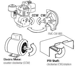
    We also need to consider the type of drive option that will be used.  For instance, when using an electric motor versus a gas or diesel engine, there are varying drive constant factors, as well.  More on this below in the post.

    Horsepower Sizing Examples Explained

    Example 1: Plunger pump rated flow is 4 gpm at 2000 psi. “EBH” or Electric Brake Horsepower required would be 4 x 2000 = 8000 divided by 1460 = 5.48.  This equation shows us that we would require an electric motor with at least 5.48 horse power output to allow the pump to operate at peak performance. In this instance you would most likely need to use a 7-1/2 HP electric motor as most motor brands are generally 1HP, 1.5HP, 2HP, 3HP, 5HP, 7.5HP, 10HP, 15HP, 20HP, 25HP, etc.

    It is important to note that electric motors have a rated horsepower and your specific application will have a required horsepower.  Required specifies the horsepower needed to produce the desired output flow and pressure.  While, rated horsepower defines the horsepower at which the motor is rated.  For instance, if the application requires a 13 HP motor, one would need to select a motor that is rated for 15 HP (there is not an electric motor rated for 13 HP or 14 HP).  Best practice is to select a motor that has a rated horsepower which exceeds your required application horsepower.

    Example 2: Diaphragm pump rated flow is 12 gpm at 500 psi. The EBH would be calculated as such: 12 x 500 = 6000 divided by 1370 = 4.38 This would require an electric motor with at least 4.38 horsepower output to allow this pump to operate at peak performance.

    Specialty Applications - Diesel Transfer Horse Power Sizing

    For calculating gas or diesel engine horsepower requirements, a general rule is to take EBH required x 2.0. Example 1 above would require 5.48 EBH x 2. 0 = 10.96 engine horsepower requirement. Therefore you would need a gas or diesel engine that will develop at least 10.96 horsepower to allow the pump to operate at peak performance.

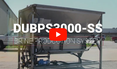
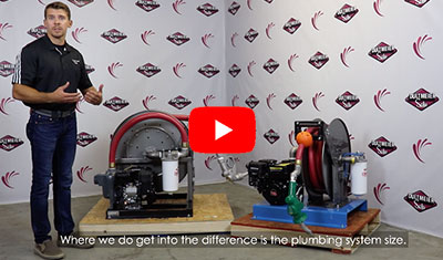
    You can look at some diesel transfer units (centrifugal pump) that we have sized specifically for flow rates at the nozzle.  We have multiple offerings that are designed to produce flow rates through a plumbing system.  When calculating, we figure in the Total Dynamic Head of the plumbing system.  In the case of our Diesel Transfer Skids, that means the pressure loss through the hose reel, 32ft of hose (inside diameter varies based upon specific unit) and a discharge nozzle.  We use a self-priming centrifugal pump in these skid systems.  When dealing with self-primer centrifugal pumps a safe efficiency factor to use is 50% efficiency.

    When using gas or diesel engines to power pumps, depending on specific brands, “engine” horsepower requirements could be reduced slightly in some instances.  For instance, some engines may have a higher compression or provide more torque as a result of enhance production practices.  This is generally a smaller factor but something to consider when powering a pump with an engine.

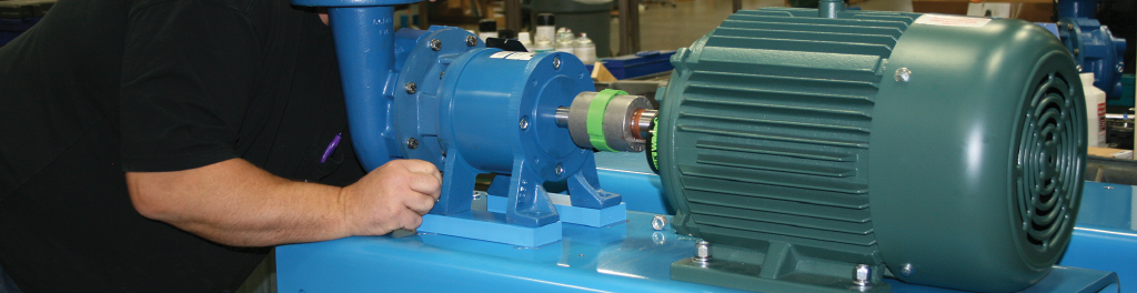
    Centrifugal Pump Horsepower Sizing

    A major difference in sizing centrifugal pumps lies in the size, or trim, of the impeller.  Based upon the solution, desired flow rates, and TDH in the plumbing system - we will size a pump to have a certain impeller trim and this directly correlates to the required horse power.

    Generally speaking, we use pump curves to assist in sizing a centrifugal pump for a specific application.  A pump will ALWAYS operate on it's curve.  That's why it is vital to accurately determine our desired output flow rate, TDH, and solution being transferred.  All of these factors, and actually many more like temperature and viscosity can, and will, affect the required horse power and impeller size of a centrifugal pump.

    We have multiple tools at our disposal to assist with this process.  One of them comes from a supplier of ours, Wilo.  Dultmeier Sales' expertise paired with the expertise of Wilo helps us to provide a value-added service for our customers in pump/motor sizing for many applications.

    Standard Efficient vs. Premium Efficient Electric Motors

    Another important note to make is the difference between a standard efficient motor and a premium efficient motor.  With the passing of Department of Energy regulations in January 2020 - many pumps (specifically straight centrifugal pumps) are now held to a certain degree of efficiency standards.  The main goal being power consumption.  Premium efficient motors are designed to be just that...much more efficient than a standard efficient motor.

    Many pump manufacturers have since, or are in the process of switching, to premium efficient motors to assist in ensuring their pump products meet the mandated efficiency standards.  Some manufacturers were able to re-engineer their pumps to meet the regulations - while others needed to redesign the pumps and upgrade to premium efficient motors.

    Be aware, in some larger NEMA frame motors, the premium efficient option can boast a larger footprint.  If your motor footprints do not match, this could cause an issue when you go to install the replacement motor.  This is an important thing to consider when replacing standard efficient motors.

    Service Factor in Electric Motors

    Lastly, we want to consider the service factor in an electric motor of choice.  A common service factor that many motor manufacturers use is 1.15.  This means if your horsepower is rated to 20 HP then you actually have some leeway to go slightly beyond the rating - if necessary.  20 HP x 1.15 Service Factor = 23 HP.  If our application had a required horsepower of 22.25 HP we could select this example motor with a service factor of 1.15.

    While it's certainly not advised to select the example 20 HP motor in this instance - it could work.  We would always caution on the side of error and advise the end user to select a rated 25 HP motor.

    We certainly hope that this post provided useful content.  As always, should you have any questions about pump sizing - don't hesitate to call us at 888-677-5054.  Be good out there.

    Fuel Transfer Pump Unit

    Looking for that perfect fuel transfer pump unit?  Look no further.  We assemble these units in Omaha, Nebraska in our production facility.  These fuel transfer pump units are available in either 1" transfer or 1.5" transfer capacity - flow characteristics vary drastically between the two versions.

    The Dilemma & Our Solution for You

    The 1" fuel transfer pump unit (DUFPU1P) will produce a flow rate of 32 GPM - at the nozzle. This is a true representation of the flow rate that the end user can expect - at the end of the plumbing system.  While competitive systems will notate "max flow rate", many of them are portraying the flow rate the fuel transfer pump outputs at an open discharge.  Open discharge means unrestricted flow and isn't an accurate representation of what an end user will experience, in terms of flow rate at the nozzle, once the fuel transfer pump is installed into a plumbing system.  Here is a quick example of how friction loss is calculated through a plumbing system to determine flow rate - at the nozzle.

    Our 1.5" fuel transfer pump unit will produce a flow rate of 60 GPM - at the nozzle.  Most 12V diesel fuel transfer pumps will produce a flow rate of approximately 18-20 GPM at the nozzle.  This is making the assumption the plumbing system consists of approximately 30 feet of 1" fuel transfer hose.

    By making the transition from lower volume 12 Volt or 115 Volt fuel transfer pumps to the 1" DUFPU1P, end users can effectively decrease their fill times by 78%.  If you choose to bump up to the, larger, DUFPU1.5P you can decrease fill times by 233%.

    That is a serious cost savings when looking at the operational expenses of paying operators to wait around while large equipment fuel tanks are being filled.  If you are able to save 15 minutes of fill time, per fill, how much money does that save you in a week?  How about a month or a year?

    Reduce waste, reduce cost, and increase efficiencies of your operation.  Bigger, faster, stronger is the name of the game and these Dultmeier fuel transfer pump units will help you achieve that status.

    Either fuel pump transfer unit option, that we manufacture, is fitted with the MP Pumps PetrolMaxx 2" self priming diesel fuel transfer pump.  These fuel pump transfer units are designed to safely handle diesel or bio-diesel fuels and significantly reduce operating expenses and improve the efficiency of your operation.

    Product Demonstration

    Our, larger volume, DUFPU1.5P boasts the following features:

    • PowerPro 6.5 HP manual start engine with C.A.R.B. rating.
    • MP PetrolMaxx 2" self-priming cast iron pump with Type 21 Viton® mechanical seal designed for diesel fuel
    • Hannay spring rewind hose reel
    • Husky high flow automatic nozzle with swivel.
    • Cimtek 1-1/2" 60 GPM fuel filter with 2-30 micron Hydrosorb elements,
    • 38' of 1-1/2" fuel transfer hose and Husky 1690 1-1/2" high flow automatic nozzle.
    • Mounted on steel base plate (powder-coat finish)


    Here is a video to help further display the unit.  Enjoy!

    (0) Matching Pump Rotation

    How do I match my pump rotation?  This is a commonality that we address on almost a daily basis but many people do not understand how to accomplish this task.  At Dultmeier Sales we are glad to help out and explain over the phone or you can get your answer right here:

    First off, let's address how we look at a pump - the direction of rotation is always determined when FACING THE SHAFT.  Centrifugal pumps are available in two options, either Counter Clockwise (CCW) or Clockwise (CW).  To match the pump shaft with a drive shaft we always MATCH THE OPPOSITE ROTATION.

    A gasoline engine will match up to a CW drive centrifugal pump.  A front tractor crankshaft PTO rotates in CCW direction and therefore must be mated to a CW centrifugal pump.  While a rear PTO shaft drive (CW rotation) application must be mated to a CCW pump.  This is somewhat counter intuitive to those new to the concept but a "standard drive" centrifugal pump will actually be CCW rotation. Therefore, a "reverse" drive pump is actually CW.

    Ace Pump Logo


    Confused yet?  Check out Ace Pumps description for further clarification along with pictures.  A common symptom of not properly matching shaft rotation is no pressure generation by the pump.  We receive calls from people describing that their brand new pump won't create any pressure and immediately point at the pump as the culprit.  More often than not, it's not the pump's fault - generally there is an application error or human error causing the issue.  In the scenario described above the first thing to confirm is that we have the correct pump shaft rotation matched with drive shaft choice.  More often than not, this is the root of the headache.  If you are still struggling give us a buzz and we will be happy to lend a hand.


    Matching Pump Rotation to Drive Units


    Let us know if this was useful content.  We certainly hope so.  If there are other topics you would like addressed in future posts, by all means, let us know!

    Be good out there.